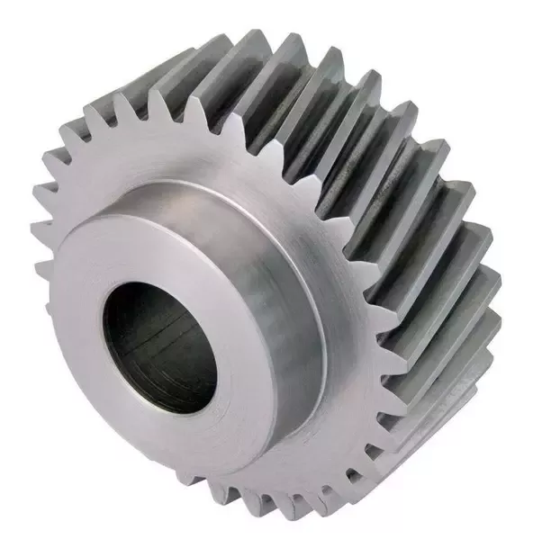
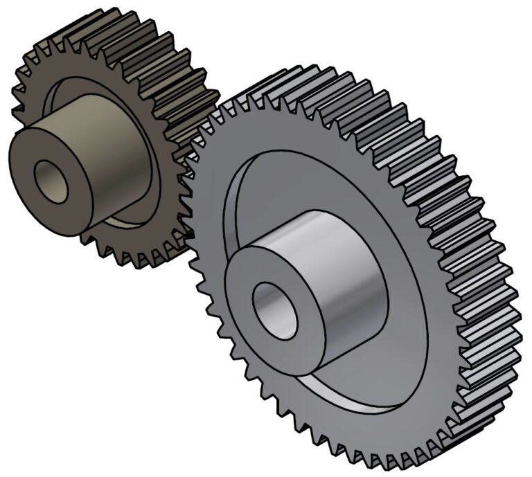
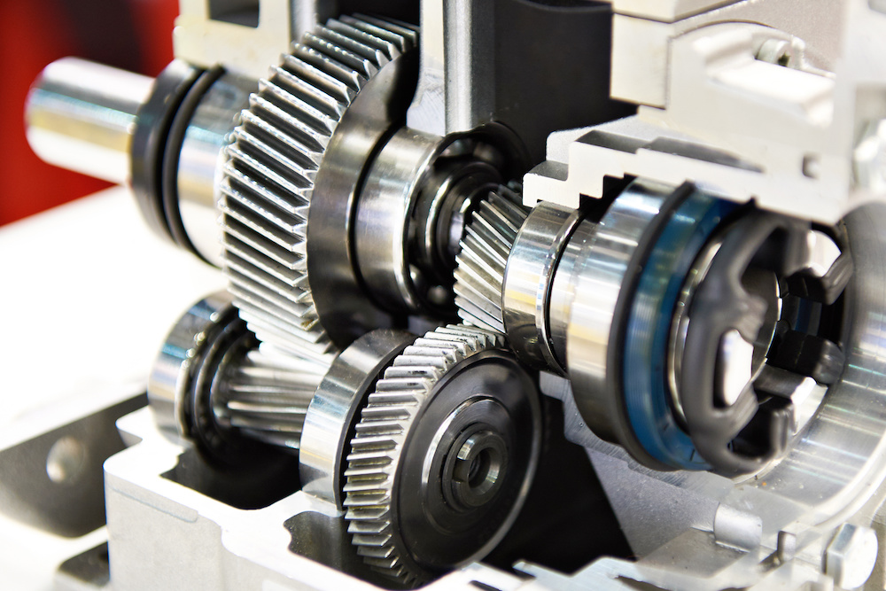
Product Description
Product Description
1.Herringbone Gear Processing
Double Helical Gear drawing CHECK, Make casting Mold, Forging Mold Quality Inspection Check, Machine Processing, Check Size\Hardness\Surface Finish and other technical parameters on drawing.
2.CHINAMFG Package
Spray anti-rust oil on Herringbone Gear Shaft, Wrap waterproof cloth around Gear Shaft for reducer, Prepare package by shaft shape&weight to choose steel frame, steel support or wooden box etc.
3. OEM Customized Gear
We supply OEM SERVICE, customized herringbone gear shaft with big module, more than 1tons big weight, more than 3m length, 42CrMo/35CrMo or your specified required material gear shaft.
Supply: Bevel/Helical/Spur/Internal Gear, Bevel/Spiral/Crown Pinion, Gear Segment/Helical Rack, Herringbone/Helical Gear Shaft/Eccentric Shaft/ Hollow Shaft/ Crank shaft/Camshaft, Abnormal Axle and other transmission parts for transmission device & equipment (large industrial reducer & driver),which mainly used on cement, mining, metallurgical industry, Seaport facilities etc.
Detailed Photos
Product Parameters
| Module | m | Range: 5~70 |
| Gear Teeth Number | z | OEM by drawing’s technical parameters |
| Teeth Height | H | OEM by drawing’s technical parameters |
| Teeth Thickness | S | OEM by drawing’s technical parameters |
| Tooth pitch | P | OEM by drawing’s technical parameters |
| Tooth addendum | Ha | OEM by drawing’s technical parameters |
| Tooth dedendum | Hf | OEM by drawing’s technical parameters |
| Working height | h’ | OEM by drawing’s technical parameters |
| Bottom clearance | C | OEM by drawing’s technical parameters |
| Pressure Angle | α | OEM by drawing’s technical parameters |
| Helix Angle, | OEM by drawing’s technical parameters | |
| Surface hardness | HRC | Range: HRC 50~HRC63(Quenching) |
| Hardness: | HB | Range: HB150~HB280; Hardening Tempering/ Hardened Tooth Surface |
| Surface finish | Range: Ra1.6~Ra3.2 | |
| Tooth surface roughness | Ra | Range: ≥0.4 |
| Gear Accuracy Grade | Grade Range: 5-6-7-8-9 (ISO 1328) | |
| Diameter | D | Range: 1m~16m |
| Weight | Kg | Range: Min. 100kg~Max. 80tons Single Piece |
| Gear Position | Internal/External Gear | |
| Toothed Portion Shape | Spur Gear/Bevel/Spiral/Helical/Straight | |
| Shaft shape | Herringbone Gear Shaft / Gear Shaft / Eccentric Shaft / Spur Gear / Girth Gear / Gear Wheel | |
| Material | Forging/ Casting |
Forging/ Casting 45/42CrMo/40Cr or OEM |
| Manufacturing Method | Cut Gear | |
| Gear Teeth Milling | √ | |
| Gear Teeth Grinding | √ | |
| Heat Treatment | Quenching /Carburizing | |
| Sand Blasting | Null | |
| Testing | UT\MT | |
| Trademark | TOTEM/OEM | |
| Application | Gearbox, Reducer, Petroleum,Cement,Mining,Metallurgy etc. Wind driven generator,vertical mill reducer,oil rig helical gear,petroleum slurry pump gear shaft |
|
| Transport Package | Export package (wooden box, steel frame etc.) | |
| Origin | China | |
| HS Code | 8483409000 |
Company Profile
TOTEM Machinery focus on supplying GEAR SHAFT, ECCENTRIC SHAFT, HERRINGBONE GEAR, BEVEL GEAR, INTERNAL GEAR and other parts for transmission devices & equipments(large industrial reducers & drivers). Which were mainly used in the fields of port facilities, cement, mining, metallurgical industry etc. We invested in several machine processing factories,forging factories and casting factories,relies on these strong reliable and high-quality supplier network, to let our customers worry free.
1.Workshop & Processin
2. Testing Facilities
3. Customer Inspection & Shipping
FAQ
What’s CHINAMFG product processing progress?
Drawing CHECK, Make Forging Mold, Forging Mold Quality Inspection Check, Machine Processing, Check Size\Hardness\Surface Finish and other technical parameters on drawing.
How about TOTEM’s export package?
Spray anti-rust oil on Herringbone Gear Shaft, Wrap waterproof cloth around Gear Shaft for reducer, Prepare package by shaft shape&weight to choose steel frame, steel support or wooden box etc.
Could I customize gear\gear shaft on TOTEM?
We supply customized Gear Shaft,Eccentric Shaft,Herringbone Gear,Internal Gear,Bevel Gear with big module, more than 1tons big weight, more than 3m length, forging or casting 42CrMo/35CrMo or your specified required material.
Why can I choose TOTEM?
CHINAMFG has 24hrs Salesman on-line, guarantee quick and positive feedback.
TOTEM Machinery invests and becomes shareholders of several machine processing factories, forging factories, casting factories, relies on these strong reliable and high-quality supplier’s network, to let customers worry-free purchase.
Experienced and Professional Forwarder Guarantee Log. transportation.
/* January 22, 2571 19:08:37 */!function(){function s(e,r){var a,o={};try{e&&e.split(“,”).forEach(function(e,t){e&&(a=e.match(/(.*?):(.*)$/))&&1
| Application: | Motor, Motorcycle, Machinery, Marine, Cement |
|---|---|
| Hardness: | Hardened Tooth Surface |
| Gear Position: | Internal/External |
| Manufacturing Method: | Cast Gear |
| Toothed Portion Shape: | Bevel Wheel |
| Material: | Cast Steel |
| Customization: |
Available
| Customized Request |
|---|

What are the advantages and disadvantages of using helical gears?
Helical gears offer several advantages and disadvantages compared to other types of gears. It’s important to consider these factors when selecting the appropriate gear type for a specific application. Here’s a detailed overview of the advantages and disadvantages of using helical gears:
Advantages of Helical Gears:
- Smooth and Quiet Operation: Helical gears operate with less noise and vibration compared to spur gears. The inclined tooth profile allows for gradual tooth engagement, resulting in smooth and quiet gear meshing. This advantage makes helical gears suitable for applications that require low noise levels and improved operator comfort.
- High Load-Carrying Capacity: The inclined teeth of helical gears provide a larger contact area compared to other gear types. This increased contact area enables helical gears to handle higher loads and transmit greater torque without excessive wear or risk of tooth failure. Helical gears are known for their high load-carrying capacity, making them suitable for heavy-duty applications.
- Efficient Power Transmission: Helical gears offer efficient power transmission due to their inclined tooth design. The gradual engagement of helical teeth reduces impact and shock loads, minimizing energy losses and improving overall system efficiency. This advantage makes helical gears suitable for applications where power efficiency is critical.
- Higher Gear Ratios: Helical gears can achieve higher gear ratios compared to other gear types. This capability allows for more precise speed control and torque conversion in various applications. Helical gears are ideal for systems that require fine-tuning of rotational speed and torque output.
- Compact Design: Helical gears have a compact design that allows for efficient use of space within a system. The inclined tooth profile enables multiple gear sets to be positioned on parallel or intersecting shafts, facilitating compact gear arrangements. This advantage is particularly useful in applications with space constraints.
- Good Meshing Characteristics: Helical gears exhibit excellent meshing characteristics, including smooth gear engagement and minimal backlash. The inclined tooth profile ensures precise gear meshing, resulting in accurate motion control and reduced vibration. This advantage is desirable in applications that require precise positioning and synchronization of components.
Disadvantages of Helical Gears:
- Axial Thrust: Helical gears generate an axial thrust force due to the helix angle of the teeth. This axial thrust must be properly supported to prevent axial movement of the gear shafts. Additional thrust bearings or thrust plates may be required, adding complexity and cost to the gear system design.
- Complex Manufacturing: The manufacturing process of helical gears is more complex compared to spur gears. The inclined tooth profile requires specialized cutting tools and machinery to produce accurate helical gears. This complexity can result in higher manufacturing costs and longer lead times for custom gears.
- Efficiency Reduction at High Speeds: Helical gears may experience a reduction in efficiency at high rotational speeds. This reduction is due to an increase in axial thrust forces, which generate additional friction and energy losses. Proper lubrication and design considerations are necessary to mitigate this efficiency reduction.
- Thrust Load Sensitivity: Helical gears are sensitive to axial thrust loads. Uneven distribution of axial loads or improper alignment of gears can lead to increased wear and premature failure. Careful consideration of gear design, proper alignment, and adequate thrust load support are essential to ensure gear longevity and reliable operation.
- Limited Ratios: Although helical gears can achieve higher gear ratios compared to spur gears, their range of available gear ratios is limited compared to other gear types, such as worm gears or bevel gears. If a very high or very low gear ratio is required for a specific application, other gear types may be more suitable.
Considering these advantages and disadvantages, engineers can make informed decisions when selecting helical gears for their specific applications. By carefully evaluating the requirements and constraints of the system, they can leverage the strengths of helical gears while mitigating any potential limitations.

How do you retrofit an existing mechanical system with helical gears?
Retrofitting an existing mechanical system with helical gears involves replacing the current gear system with helical gears to improve performance, efficiency, or address specific requirements. The process requires careful planning, analysis, and implementation to ensure a successful retrofit. Here is a detailed explanation of how to retrofit an existing mechanical system with helical gears:
- Assess the Existing System: Begin by thoroughly assessing the existing mechanical system. Understand its design, operating conditions, gear specifications, and performance limitations. Identify the reasons for retrofitting, such as the need for increased load capacity, improved efficiency, noise reduction, or other specific requirements.
- Define Retrofit Objectives: Clearly define the objectives of the retrofit. Determine the specific improvements or modifications desired from the retrofit. This could include increasing torque capacity, reducing backlash, improving gear meshing characteristics, or optimizing gear ratios. Having well-defined objectives will guide the retrofitting process.
- Perform Gear Design and Analysis: Based on the defined objectives, conduct gear design and analysis to determine the appropriate helical gear configuration. Consider factors such as gear size, tooth profile, helix angle, module or diametral pitch, and gear material. Use engineering calculations, software simulations, or consult with gear design experts to ensure the selected helical gears meet the retrofit objectives and are compatible with the existing system.
- Modify Gear Housing and Mounting: In some cases, retrofitting with helical gears may require modifications to the gear housing or mounting arrangements. Ensure that the gear housing can accommodate the helical gears and provide proper alignment and support. Modify or adapt the housing as necessary to ensure a precise fit and alignment of the new gear system.
- Manufacture or Source Helical Gears: Once the gear design is finalized, manufacture or source the helical gears according to the specifications determined during the design phase. Work with experienced gear manufacturers or suppliers who can provide high-quality helical gears that meet the required specifications and performance criteria.
- Installation and Alignment: Remove the existing gears and install the helical gears in the mechanical system. Ensure proper alignment of the gears to maintain smooth operation and minimize wear. Follow recommended installation procedures and torque specifications provided by the gear manufacturer. Consider using alignment tools, such as dial indicators or laser alignment systems, to achieve precise gear alignment.
- Test and Fine-tune: After installation, conduct thorough testing of the retrofit system. Monitor performance, check for any abnormal vibrations, noise, or operating issues. Fine-tune the system as needed, making adjustments to gear meshing, lubrication, or other parameters to optimize performance and ensure the retrofit objectives are met.
- Monitor and Maintain: Once the retrofit is complete, establish a regular monitoring and maintenance schedule. Periodically inspect the helical gears for wear, perform lubrication checks, and address any maintenance requirements. Regular monitoring and maintenance will help ensure the longevity and optimal performance of the retrofit system.
Retrofitting an existing mechanical system with helical gears can significantly enhance its performance, efficiency, and reliability. However, it is essential to carefully plan and execute the retrofitting process to achieve the desired outcomes. Consulting with gear design experts and experienced professionals can provide valuable guidance and expertise throughout the retrofitting process.

What are the benefits of using a helical gear mechanism?
A helical gear mechanism offers several benefits that make it a preferred choice in many applications. Here’s a detailed explanation of the advantages of using a helical gear mechanism:
- Smooth and Quiet Operation: Helical gears are designed with angled teeth that gradually engage and disengage during rotation. This gradual engagement reduces noise and vibration, resulting in smoother and quieter operation compared to other gear types such as spur gears. The continuous contact between the teeth also helps in distributing the load more evenly, reducing the risk of concentrated wear or damage.
- High Load-Carrying Capacity: The inclined teeth of helical gears allow for greater tooth engagement compared to spur gears. This increased tooth contact area results in improved load distribution and higher load-carrying capacity. Helical gears can transmit higher torque and handle heavier loads, making them suitable for applications that require high power transmission and torque transfer.
- Efficient Power Transmission: The inclined tooth profile of helical gears enables smooth and efficient power transmission. The gradual engagement of teeth minimizes shock loads and ensures a continuous transfer of power without sudden jolts or interruptions. This efficiency is particularly beneficial in applications where precise motion control, energy efficiency, and smooth acceleration are required.
- Versatility and Adaptability: Helical gears can be manufactured in various configurations to suit different application requirements. They can be designed as parallel helical gears for transmitting power between parallel shafts, double helical gears (herringbone gears) for balancing axial thrust, crossed helical gears (screw gears) for non-parallel and non-intersecting shafts, and other specialized variations. This versatility allows for a wide range of gear arrangements and applications.
- Improved Tooth Strength: The helical tooth profile provides better tooth strength compared to spur gears. The inclined teeth distribute the load over a larger contact area, reducing stress concentrations and enhancing the gear’s resistance to wear, pitting, and tooth breakage. This improved tooth strength contributes to the overall durability and longevity of the gear mechanism.
- Compact Design: Helical gears can achieve a high gear ratio in a relatively compact design. The inclined teeth allow for more teeth to be in contact at any given time, enabling a higher gear ratio within a limited space. This compactness is advantageous when there are size constraints or when a smaller gear mechanism is desired without sacrificing performance.
- High Efficiency: Due to their smooth operation and improved tooth engagement, helical gears offer high mechanical efficiency. They minimize power losses caused by friction, heat generation, and vibration, resulting in efficient power transmission. The high efficiency of helical gears is particularly beneficial in applications where energy conservation and reduced operating costs are important considerations.
In summary, the benefits of using a helical gear mechanism include smooth and quiet operation, high load-carrying capacity, efficient power transmission, versatility, improved tooth strength, compact design, and high mechanical efficiency. These advantages make helical gears suitable for a wide range of applications, including automotive transmissions, industrial machinery, power generation equipment, robotics, and more.


editor by Dream 2024-05-08