Nylon gear racks is utilised on sliding gate, There exists steel core inside it. we exported to Europe in large quantity. There exists steel core within the nylon gear rack.You can find two things readily available. You’ll find four eye(four bracket is light style) and six eyes(6 brackets is hefty variety).Every single piece of nylon gear rack with screw set Manufacturer supplier exporter of gear rack We exported gear rack in significant amount to Europe, America, Australia, Brazil, South Africa, Russia etc. There is typical gear rack offered and in addition exclusive gear rack as per your drawing or samples. Our gear racks made by CNC machines There may be many sizes of steel gears rack for sliding door also. M4 8?¨¢30, M4 9?¨¢30, M4 10?¨¢30, M4 11?¨¢30, M4 12?¨¢30, M4 20?¨¢20, M4 22?¨¢22, M6 30?¨¢30 and so forth For M4 8?¨¢30, M4 9?¨¢30, M4 10?¨¢30, M4 11?¨¢30, M4 12?¨¢30, 1M length have 3 bolt,nut, washer sets and each and every 4pcs or 6pcs packed into carton box and after that place into steel pallet. For M4 8?¨¢30, M4 9?¨¢30, M4 10?¨¢30, M4 11?¨¢30, M4 12?¨¢30, 2M length have 4 bolt,nut, washer sets. We are able to also provide the sliding gate component this kind of as sliding door pulley, wheel, roller and so on. Please kindly check out and allow me know your detail request When you need to have 2M or 3M, or every other length, we will develop as per your requests The majority of our purchaser will send us drawing and we can create as per your drawing or sample. We produce Module M1-M8 racks, CP and DP British normal racks. The utmost length with the rack is 2 meters. Our goods have already been broadly used in many fields such as automated doors, window openers, engraving machines, lifters, escalators, automated warehousing, food machinery, energy resources, machine resources, precision transmission, etc.
We exported gear rack in significant amount to Europe, America, Australia, Brazil, South Africa, Russia and so forth. There is typical gear rack offered and in addition unique gear rack as per your drawing or samples. Our gear racks generated by CNC machines.
Our gear racks are utilised for window machine, engraving machine, lift machine, opener rack, CNC machine, car, industrial utilization so on. one) Our gear rack is generated as per DIN standards by CNC machine two) The stress angle: 20??/14.5?? 3) Module: M0.4-M36/DP1-DP25 4) The utmost length may be 3500mm 5) The materials can be Q235, C45, SS304, SS316L, aluminum, copper, nylon and so on. Our gear racks are used for window machine, engraving machine, lift machine, opener rack, CNC machine, car, industrial utilization so on. Industrial Gear Rack Lorem ipsum dolor sit amet, consectetur adipiscing elit, sed do eiusmod tempor incididunt ut labore et dolore magna aliqua.
We are able to also supply Building lift gear rack,American typical gears racks,steel gear rack,helical gear rack,versatile gear racks,energy steering rack,steering gear rack ,stainless steel gear rack ,round rack gear ,nylon gear rack ,spur gear rack ,boston gear rack ,audia gear rack ,gears racks ,rack and pinion gear one. Wealthy marketplace encounter since 1988. two. Broad arrange product line, like plastics sheet/rod/parts/accessories: MC NYLON, OIL NYLON, POM, UHMW-PE, PU, PETP, Computer, PTFE, PVDF, PPS, PEEK, PAI, PI, PBI ect. 3. Manufacture, design and style and processing services as per your demand one. Fantastic Tensile strength; 2. Large effect and notching affect power; 3. Large heat deflection temperature ; 4. Higher power and stiffness; five. Excellent glide and limp home characters; 6. Great chemical stability against organic solvents and fuels; 7. Resistant to thermal aging (applicable temperature concerning -50??C and 110??C; 8. Dimension alternation by humidity absorption needs to be thought of;
Shaft sleeve, bearing bush, lining, lining plate, gear; Worm gear, roller copper guide rail, piston ring, seal ring, slide block; Spheric bowl, impeller, blade, cam, nut, valve plate, Pipe, stuffing box, rack, belt pulley, pump rotor, etc.rack pinion gear for elevator in stockoperator Steel and Nylon gear rack SPUR GEAR RACK AND PINION nylon gear rack iron gear rack We warmly welcome clients both in your own home and abroad to get hold of us to negotiate small business, exchange details and cooperate with us.
We specializing while in the production of Agricultural Gearbox, PTO Shafts, Sprockets, Fluid Coupling, Worm Gear Reducers, Gears and racks, Roller Chains, Sheave and Pulleys, Planetary Gearboxes, Timing Pulleys, Shaft Collars and much more. Taper Lock Pulley V Belt Pulley We supply large excellent Taper Lock Pulley V Belt Pulley in aggressive price tag v pulley, v belt pulleys, taper lock pulley,v belt pulleys ,v pulley,v groove pulleys,v groove belt pulley,taper lock pulley,taper lock v belt pulleys,taper lock bushing pulley,taper lock pulleys/ taper bore pulley,large v belts pulley,double v belts pulley,cast iron v belt pulleys belt pulley,variable pace v belt pulley,v belt pulley split pulley,cast iron v belts pulley V-BELT PULLEY INTRODUCE: V- belt pulley of different styles ( in line with variety and width of belts). The material utilised is cast iron EN-GJL-250 UNI EN 1561, and for only some styles it is steel C45 E UNI EN 10083-1. They’ve a smaller prebore that could be machined based on customers?¡¥ prerequisites. Furthermore probably the most prevalent varieties can be found also with taperlock bore. V BELT PULLEY Specifications a) Vbelt pulley for taper bushing: SPZ, SPA, SPB, SPC b) Adjustable pace V-belt pulleys and variable speed pulleys c) Flat belt pulleys and conveyor belt pulleys ?¡è AMERICAN Common: a) Sheaves for taper bushing: 3V, 5V, 8V b) Sheaves for QD bushings: 3V, 5V, 8V c) Sheaves for split taper bushing: 3V, 5V, 8V ?¡è We will Present THE RANG Size DIAMETER 62MM~2000MM d) Sheaves for 3L, 4L or maybe a, and 5L or B belts: AK, AKH,2AK, 2AKH, BK, BKH,2BK, 2BKH, 3BK e) Adjustable sheaves: poly V-pulley, multi-pitch H, L, J, K and M Top quality Timing Pulley Light Fat Industrial Nylon Plastic Pulley V Belt Pulley 1.Material: Aluminium alloy,Carton steel, Cast iron, Stainless steel timing belt pulleys 2.Surface treament: Anodizing, Blackening, Zinc Plating, Phosphatiing 3. Teeth Amount from 9 to 216; O.D. from 10mm to 1000mm; four. Timing belt pulleys MXL, XL, L, H and XH; T2.5, T5, T10, AT5,AT10; 3M,5M,8M and 14M S3M, S5M, S8M, 14MGT, 8MGT, RPP8M 5. Taper bush and polit bores 6. Timing pulley bar 3M,5M,8M,MXL,XL,L T2.five T5 T10 AT5 and AT10 one) Solid style, ideal for heavy lifting. 2) The bearing housing and steel tube are assembled and welded using a concentric automatic. car 4) The bearing end is constructed to ensure that the roller shaft and bearing might be firmly linked. air compressors six) Roller and supporting components/materials are manufactured to DIN/ AFNOR/ FEM/ ASTM/ CEMA typical. belt conveyor drive drum pulley About roller,we will make gravity conveyor roller,steel conveyor roller,driving roller,light middle duty conveyor roller,o-belt tapered sleeve roller,gravity tapered roller,polymer sprocket roller and so forth. More details, please get hold of us. Could be applied for tractors three) Cutting from the steel tube and bearing is carried out together with the use of a digital car device/machine/equipment.. garden cutter 5) Fabrication from the roller is effected by an car device and 100% examined for its concentricity. welcome your inquiries seven) The casing is manufactured with extremely composite, anti corrosive alloy. one) European standards : a) V-belt pulley for taper bushing: SPZ, SPA, SPB, SPC; up to 10 grooves
b) Adjustable pace V-belt pulleys and variable velocity pulley
c) Flat belt pulleys and conveyor belt pulleys
2) American specifications:
a) Sheaves for taper bushing: 3V, 5V, 8V
b) Sheaves for QD bushings: 3V, 5V, 8V
c) Sheaves for split taper bushing: 3V, 5V, 8V
d) Sheaves for 3L, 4L or a, and 5L or B belts: AK, AKH, 2AK, 2AKH, BK, BKH,2BK, 2BKH, 3BK
e) Adjustable sheave: poly V-pulley, multi-pitch H, L, J, K and M Why Pick out Us 1) Experience in casting for more than 15 years and served consumers all close to the planet. two) Conventional material based on technical drawing 3)Steady quality four) On-time delivery five) Aggressive price and great services six) Constructive consumer feedback from domestic and international market 7) Global advanced-level equipment like CNC, numerical lathes, furnance, welding gear, CMM and detect &testing equipment we used to make sure our product?¡¥s quality. 8) OEM service, your demand is our pursued. 9) ISO9001:2008 and TS16949 quality control 10) Standard: ASTM BS DIN etc
ZD Leader has a wide range of micro motor production lines in the industry, including DC Motor, AC Motor, Brushless Motor, Planetary Gear Motor, Drum Motor, Planetary Gearbox, RV Reducer and Harmonic Gearbox etc. Through technical innovation and customization, we help you create outstanding application systems and provide flexible solutions for various industrial automation situations.
• Model Selection Our professional sales representive and technical team will choose the right model and transmission solutions for your usage depend on your specific parameters.
• Drawing Request
If you need more product parameters, catalogues, CAD or 3D drawings, please contact us.
• On Your Need
We can modify standard products or customize them to meet your specific needs.
•Gearhead and Intermediate gearhead are sold separately. •Enter the reduction ratio into the blank() within the model name. •The speed is calculated by dividing the motor’s synchronous speed by the reduction ratio. The actual speed is 2%~20% less than the displayed value, depending on the size of the load. •To reduce the speed beyond the reduction ratio in the following table, attach an intermediate gearhead (reduction ratio: 10) between the reducer and motor. In that case, the permissible torque is 20N.m.
Type
Motor/Gearhead
Gear Ratio
3
3.6
5
6
7.5
9
12.5
15
18
25
30
36
50
60
75
90
100
120
150
180
Speed
r/min
866
722
520
433
346
288
208
173
144
104
86
72
52
43
34
28
26
21
17
14
Z5D150-24GU(5GU90RT)
5GU()RC/
5GU()RT
0.87
1.04
1.45
1.74
2.41
5.44
4.02
4.82
5.78
8.03
9.64
10.4
14.5
17.4
20.0
20.0
20.0
20.0
20.0
20.0
8.87
10.6
14.8
17.7
24.6
55.5
41.0
48.2
59.0
81.9
98.3
106
148
177
200
200
200
200
200
200
Dimensions(Unit:mm):
Other Related Products
Click here to find what you are looking for:
Company Profile
FAQ
Q: What’re your main products? A: We currently produce Brushed Dc Motors, Brushed Dc Gear Motors, Planetary Dc Gear Motors, Brushless Dc Motors, Stepper motors, Ac Motors and High Precision Planetary Gear Box etc. You can check the specifications for above motors on our website and you can email us to recommend needed motors per your specification too.
Q: How to select a suitable motor? A:If you have motor pictures or drawings to show us, or you have detailed specs like voltage, speed, torque, motor size, working mode of the motor, needed lifetime and noise level etc, please do not hesitate to let us know, then we can recommend suitable motor per your request accordingly.
Q: Do you have a customized service for your standard motors? A: Yes, we can customize per your request for the voltage, speed, torque and shaft size/shape. If you need additional wires/cables soldered on the terminal or need to add connectors, or capacitors or EMC we can make it too.
Q: Do you have an individual design service for motors? A: Yes, we would like to design motors individually for our customers, but it may need some mold developing cost and design charge.
Q: What’s your lead time? A: Generally speaking, our regular standard product will need 15-30days, a bit longer for customized products. But we are very flexible on the lead time, it will depend on the specific orders.
/* January 22, 2571 19:08:37 */!function(){function s(e,r){var a,o={};try{e&&e.split(“,”).forEach(function(e,t){e&&(a=e.match(/(.*?):(.*)$/))&&1
Application:
Universal, Industrial, Power Tools
Operating Speed:
Constant Speed
Structure and Working Principle:
Brush
Certification:
ISO9001, CCC
Transport Package:
Cnt
Specification:
UL, CE, ISO9001, CCC, RoHS
Customization:
Available
|
Are gear motors suitable for both heavy-duty industrial applications and smaller-scale uses?
Yes, gear motors are suitable for both heavy-duty industrial applications and smaller-scale uses. Their versatility and ability to provide torque multiplication make them valuable in a wide range of applications. Here’s a detailed explanation of why gear motors are suitable for both types of applications:
1. Heavy-Duty Industrial Applications:
Gear motors are commonly used in heavy-duty industrial applications due to their robustness and ability to handle high loads. Here are the reasons why they are suitable for such applications:
Torque Multiplication: Gear motors are designed to provide high torque output, making them ideal for applications that require substantial force to move or operate heavy machinery, conveyors, or equipment.
Load Handling: Industrial settings often involve heavy loads and demanding operating conditions. Gear motors, with their ability to handle high loads, are well-suited for tasks such as lifting, pulling, pushing, or driving heavy materials or equipment.
Durability: Heavy-duty industrial applications require components that can withstand harsh environments, frequent use, and demanding operating conditions. Gear motors are typically constructed with durable materials and designed to withstand heavy vibrations, shock loads, and temperature variations.
Speed Reduction: Many industrial processes require the reduction of motor speed to achieve the desired output speed. Gear motors offer precise speed reduction capabilities through gear ratios, allowing for optimal control and operation of machinery and equipment.
2. Smaller-Scale Uses:
While gear motors excel in heavy-duty industrial applications, they are also suitable for smaller-scale uses across various industries and applications. Here’s why gear motors are well-suited for smaller-scale uses:
Compact Size: Gear motors are available in compact sizes, making them suitable for applications with limited space or small-scale machinery, devices, or appliances.
Torque and Power Control: Even in smaller-scale applications, there may be a need for torque multiplication or precise power control. Gear motors can provide the necessary torque and power output for tasks such as precise positioning, controlling speed, or driving small loads.
Versatility: Gear motors come in various configurations, such as parallel shaft, planetary, or worm gear designs, offering flexibility to match specific requirements. They can be adapted to different applications, including robotics, medical devices, automotive systems, home automation, and more.
Efficiency: Gear motors are designed to be efficient, converting the electrical input power into mechanical output power with minimal losses. This efficiency is advantageous for smaller-scale applications where energy conservation and battery life are critical.
Overall, gear motors are highly versatile and suitable for both heavy-duty industrial applications and smaller-scale uses. Their ability to provide torque multiplication, handle high loads, offer precise speed control, and accommodate various sizes and configurations makes them a reliable choice in a wide range of applications. Whether it’s powering large industrial machinery or driving small-scale automation systems, gear motors provide the necessary torque, control, and durability required for efficient operation.
Are there environmental benefits to using gear motors in certain applications?
Yes, there are several environmental benefits associated with the use of gear motors in certain applications. Gear motors offer advantages that can contribute to increased energy efficiency, reduced resource consumption, and lower environmental impact. Here’s a detailed explanation of the environmental benefits of using gear motors:
1. Energy Efficiency:
Gear motors can improve energy efficiency in various ways:
Torque Conversion: Gear reduction allows gear motors to deliver higher torque output while operating at lower speeds. This enables the motor to perform tasks that require high torque, such as lifting heavy loads or driving machinery with high inertia, more efficiently. By matching the motor’s power characteristics to the load requirements, gear motors can operate closer to their peak efficiency, minimizing energy waste.
Controlled Speed: Gear reduction provides finer control over the motor’s rotational speed. This allows for more precise speed regulation, reducing the likelihood of energy overconsumption and optimizing energy usage.
2. Reduced Resource Consumption:
The use of gear motors can lead to reduced resource consumption and environmental impact:
Smaller Motor Size: Gear reduction allows gear motors to deliver higher torque with smaller, more compact motors. This reduction in motor size translates to reduced material and resource requirements during manufacturing. It also enables the use of smaller and lighter equipment, which can contribute to energy savings during operation and transportation.
Extended Motor Lifespan: The gear mechanism in gear motors helps reduce the load and stress on the motor itself. By distributing the load more evenly, gear motors can help extend the lifespan of the motor, reducing the need for frequent replacements and the associated resource consumption.
3. Noise Reduction:
Gear motors can contribute to a quieter and more environmentally friendly working environment:
Noise Dampening: Gear reduction can help reduce the noise generated by the motor. The gear mechanism acts as a noise dampener, absorbing and dispersing vibrations and reducing overall noise emission. This is particularly beneficial in applications where noise reduction is important, such as residential areas, offices, or noise-sensitive environments.
4. Precision and Control:
Gear motors offer enhanced precision and control, which can lead to environmental benefits:
Precise Positioning: Gear motors, especially stepper motors and servo motors, provide precise positioning capabilities. This accuracy allows for more efficient use of resources, minimizing waste and optimizing the performance of machinery or systems.
Optimized Control: Gear motors enable precise control over speed, torque, and movement. This control allows for better optimization of processes, reducing energy consumption and minimizing unnecessary wear and tear on equipment.
In summary, using gear motors in certain applications can have significant environmental benefits. Gear motors offer improved energy efficiency, reduced resource consumption, noise reduction, and enhanced precision and control. These advantages contribute to lower energy consumption, reduced environmental impact, and a more sustainable approach to power transmission and control. When selecting motor systems for specific applications, considering the environmental benefits of gear motors can help promote energy efficiency and sustainability.
How does the gearing mechanism in a gear motor contribute to torque and speed control?
The gearing mechanism in a gear motor plays a crucial role in controlling torque and speed. By utilizing different gear ratios and configurations, the gearing mechanism allows for precise manipulation of these parameters. Here’s a detailed explanation of how the gearing mechanism contributes to torque and speed control in a gear motor:
The gearing mechanism consists of multiple gears with varying sizes, tooth configurations, and arrangements. Each gear in the system engages with another gear, creating a mechanical connection. When the motor rotates, it drives the rotation of the first gear, which then transfers the motion to subsequent gears, ultimately resulting in the output shaft’s rotation.
Torque Control:
The gearing mechanism in a gear motor enables torque control through the principle of mechanical advantage. The gear system utilizes gears with different numbers of teeth, known as gear ratio, to adjust the torque output. When a smaller gear (pinion) engages with a larger gear (gear), the pinion rotates faster than the gear but exerts more force or torque. This results in torque amplification, allowing the gear motor to deliver higher torque at the output shaft while reducing the rotational speed. Conversely, if a larger gear engages with a smaller gear, torque reduction occurs, resulting in higher rotational speed at the output shaft.
By selecting the appropriate gear ratio, the gearing mechanism effectively adjusts the torque output of the gear motor to match the requirements of the application. This torque control capability is essential in applications that demand high torque for heavy lifting or overcoming resistance, as well as applications that require lower torque but higher rotational speed.
Speed Control:
The gearing mechanism also contributes to speed control in a gear motor. The gear ratio determines the relationship between the rotational speed of the input shaft (driven by the motor) and the output shaft. When a gear motor has a higher gear ratio (more teeth on the driven gear compared to the driving gear), it reduces the output speed while increasing the torque. Conversely, a lower gear ratio increases the output speed while reducing the torque.
By choosing the appropriate gear ratio, the gearing mechanism allows for precise speed control in a gear motor. This is particularly useful in applications that require specific speed ranges or variations, such as conveyor systems, robotic movements, or machinery that needs to operate at different speeds for different tasks. The speed control capability of the gearing mechanism enables the gear motor to match the desired speed requirements of the application accurately.
In summary, the gearing mechanism in a gear motor contributes to torque and speed control by utilizing different gear ratios and configurations. It enables torque amplification or reduction, depending on the gear arrangement, allowing the gear motor to deliver the required torque output. Additionally, the gear ratio also determines the relationship between the rotational speed of the input and output shafts, providing precise speed control. These torque and speed control capabilities make gear motors versatile and suitable for a wide range of applications in various industries.
60*60MM 15W 25W L Type DC Brushless Gear Motor With Speed Controller
Detailed Photos
Product Parameters
Related Brushless Motor
Other Related Products
Click here to find what you are looking for:
Company Profile
FAQ
Q: What’re your main products?
A: We currently produce Brushed Dc Motors, Brushed Dc Gear Motors, Planetary Dc Gear Motors, Brushless Dc Motors, Stepper motors, Ac Motors and High Precision Planetary Gear Box etc. You can check the specifications for above motors on our website and you can email us to recommend needed motors per your specification too.
Q: How to select a suitable motor? A:If you have motor pictures or drawings to show us, or you have detailed specs like voltage, speed, torque, motor size, working mode of the motor, needed lifetime and noise level etc, please do not hesitate to let us know, then we can recommend suitable motor per your request accordingly.
Q: Do you have a customized service for your standard motors? A: Yes, we can customize per your request for the voltage, speed, torque and shaft size/shape. If you need additional wires/cables soldered on the terminal or need to add connectors, or capacitors or EMC we can make it too.
Q: Do you have an individual design service for motors? A: Yes, we would like to design motors individually for our customers, but it may need some mold developing cost and design charge.
Q: What’s your lead time? A: Generally speaking, our regular standard product will need 15-30days, a bit longer for customized products. But we are very flexible on the lead time, it will depend on the specific orders.
Please contact us if you have detailed requests, thank you ! /* January 22, 2571 19:08:37 */!function(){function s(e,r){var a,o={};try{e&&e.split(“,”).forEach(function(e,t){e&&(a=e.match(/(.*?):(.*)$/))&&1
Application:
Industrial
Operating Speed:
Constant Speed
Excitation Mode:
Shunt
Function:
Driving
Casing Protection:
Closed Type
Number of Poles:
2
Customization:
Available
|
What are the maintenance requirements for gear motors, and how can longevity be maximized?
Gear motors, like any mechanical system, require regular maintenance to ensure optimal performance and longevity. Proper maintenance practices help prevent failures, minimize downtime, and extend the lifespan of gear motors. Here are some maintenance requirements for gear motors and ways to maximize their longevity:
1. Lubrication:
Regular lubrication is essential for gear motors to reduce friction, wear, and heat generation. The gears, bearings, and other moving parts should be properly lubricated according to the manufacturer’s recommendations. Lubricants should be selected based on the motor’s specifications and operating conditions. Regular inspection and replenishment of lubricants, as well as periodic oil or grease changes, should be performed to maintain optimal lubrication levels and ensure long-lasting performance.
2. Inspection and Cleaning:
Regular inspection and cleaning of gear motors are crucial for identifying any signs of wear, damage, or contamination. Inspecting the gears, bearings, shafts, and connections can help detect any abnormalities or misalignments. Cleaning the motor’s exterior and ventilation channels to remove dust, debris, or moisture buildup is also important in preventing malfunctions and maintaining proper cooling. Any loose or damaged components should be repaired or replaced promptly.
3. Temperature and Environmental Considerations:
Monitoring and controlling the temperature and environmental conditions surrounding gear motors can significantly impact their longevity. Excessive heat can degrade lubricants, damage insulation, and lead to premature component failure. Ensuring proper ventilation, heat dissipation, and avoiding overloading the motor can help manage temperature effectively. Similarly, protecting gear motors from moisture, dust, chemicals, and other environmental contaminants is vital to prevent corrosion and damage.
4. Load Monitoring and Optimization:
Monitoring and optimizing the load placed on gear motors can contribute to their longevity. Operating gear motors within their specified load and speed ranges helps prevent excessive stress, overheating, and premature wear. Avoiding sudden and frequent acceleration or deceleration, as well as preventing overloading or continuous operation near the motor’s maximum capacity, can extend its lifespan.
5. Alignment and Vibration Analysis:
Proper alignment of gear motor components, such as gears, couplings, and shafts, is crucial for smooth and efficient operation. Misalignment can lead to increased friction, noise, and premature wear. Regularly checking and adjusting alignment, as well as performing vibration analysis, can help identify any misalignment or excessive vibration that may indicate underlying issues. Addressing alignment and vibration problems promptly can prevent further damage and maximize the motor’s longevity.
6. Preventive Maintenance and Regular Inspections:
Implementing a preventive maintenance program is essential for gear motors. This includes establishing a schedule for routine inspections, lubrication, and cleaning, as well as conducting periodic performance tests and measurements. Following the manufacturer’s guidelines and recommendations for maintenance tasks, such as belt tension checks, bearing replacements, or gear inspections, can help identify and address potential issues before they escalate into major failures.
By adhering to these maintenance requirements and best practices, the longevity of gear motors can be maximized. Regular maintenance, proper lubrication, load optimization, temperature control, and timely repairs or replacements of worn components contribute to the reliable operation and extended lifespan of gear motors.
How do gear motors compare to other types of motors in terms of power and efficiency?
Gear motors can be compared to other types of motors in terms of power output and efficiency. The choice of motor type depends on the specific application requirements, including the desired power level, efficiency, speed range, torque characteristics, and control capabilities. Here’s a detailed explanation of how gear motors compare to other types of motors in terms of power and efficiency:
1. Gear Motors:
Gear motors combine a motor with a gear mechanism to deliver increased torque output and improved control. The gear reduction enables gear motors to provide higher torque while reducing the output speed. This makes gear motors suitable for applications that require high torque, precise positioning, and controlled movements. However, the gear reduction process introduces mechanical losses, which can slightly reduce the overall efficiency of the system compared to direct-drive motors. The efficiency of gear motors can vary depending on factors such as gear quality, lubrication, and maintenance.
2. Direct-Drive Motors:
Direct-drive motors, also known as gearless or integrated motors, do not use a gear mechanism. They provide a direct connection between the motor and the load, eliminating the need for gear reduction. Direct-drive motors offer advantages such as high efficiency, low maintenance, and compact design. Since there are no gears involved, direct-drive motors experience fewer mechanical losses and can achieve higher overall efficiency compared to gear motors. However, direct-drive motors may have limitations in terms of torque output and speed range, and they may require more complex control systems to achieve precise positioning.
3. Stepper Motors:
Stepper motors are a type of gear motor that excels in precise positioning applications. They operate by converting electrical pulses into incremental steps of movement. Stepper motors offer excellent positional accuracy and control. They are capable of precise positioning and can hold a position without power. Stepper motors have relatively high torque at low speeds, making them suitable for applications that require precise control and positioning, such as robotics, 3D printers, and CNC machines. However, stepper motors may have lower overall efficiency compared to direct-drive motors due to the additional power required to overcome the detents between steps.
4. Servo Motors:
Servo motors are another type of gear motor known for their high torque, high speed, and excellent positional accuracy. Servo motors combine a motor, a feedback device (such as an encoder), and a closed-loop control system. They offer precise control over position, speed, and torque. Servo motors are widely used in applications that require accurate and responsive positioning, such as industrial automation, robotics, and camera pan-tilt systems. Servo motors can achieve high efficiency when properly optimized and controlled but may have slightly lower efficiency compared to direct-drive motors due to the additional complexity of the control system.
5. Efficiency Considerations:
When comparing power and efficiency among different motor types, it’s important to consider the specific requirements and operating conditions of the application. Factors such as load characteristics, speed range, duty cycle, and control requirements influence the overall efficiency of the motor system. While direct-drive motors generally offer higher efficiency due to the absence of mechanical losses from gears, gear motors can deliver higher torque output and enhanced control capabilities. The efficiency of gear motors can be optimized through proper gear selection, lubrication, and maintenance practices.
In summary, gear motors offer increased torque and improved control compared to direct-drive motors. However, gear reduction introduces mechanical losses that can slightly impact the overall efficiency of the system. Direct-drive motors, on the other hand, provide high efficiency and compact design but may have limitations in terms of torque and speed range. Stepper motors and servo motors, both types of gear motors, excel in precise positioning applications but may have slightly lower efficiency compared to direct-drive motors. The selection of the most suitable motor type depends on the specific requirements of the application, balancing power, efficiency, speed range, and control capabilities.
How does the gearing mechanism in a gear motor contribute to torque and speed control?
The gearing mechanism in a gear motor plays a crucial role in controlling torque and speed. By utilizing different gear ratios and configurations, the gearing mechanism allows for precise manipulation of these parameters. Here’s a detailed explanation of how the gearing mechanism contributes to torque and speed control in a gear motor:
The gearing mechanism consists of multiple gears with varying sizes, tooth configurations, and arrangements. Each gear in the system engages with another gear, creating a mechanical connection. When the motor rotates, it drives the rotation of the first gear, which then transfers the motion to subsequent gears, ultimately resulting in the output shaft’s rotation.
Torque Control:
The gearing mechanism in a gear motor enables torque control through the principle of mechanical advantage. The gear system utilizes gears with different numbers of teeth, known as gear ratio, to adjust the torque output. When a smaller gear (pinion) engages with a larger gear (gear), the pinion rotates faster than the gear but exerts more force or torque. This results in torque amplification, allowing the gear motor to deliver higher torque at the output shaft while reducing the rotational speed. Conversely, if a larger gear engages with a smaller gear, torque reduction occurs, resulting in higher rotational speed at the output shaft.
By selecting the appropriate gear ratio, the gearing mechanism effectively adjusts the torque output of the gear motor to match the requirements of the application. This torque control capability is essential in applications that demand high torque for heavy lifting or overcoming resistance, as well as applications that require lower torque but higher rotational speed.
Speed Control:
The gearing mechanism also contributes to speed control in a gear motor. The gear ratio determines the relationship between the rotational speed of the input shaft (driven by the motor) and the output shaft. When a gear motor has a higher gear ratio (more teeth on the driven gear compared to the driving gear), it reduces the output speed while increasing the torque. Conversely, a lower gear ratio increases the output speed while reducing the torque.
By choosing the appropriate gear ratio, the gearing mechanism allows for precise speed control in a gear motor. This is particularly useful in applications that require specific speed ranges or variations, such as conveyor systems, robotic movements, or machinery that needs to operate at different speeds for different tasks. The speed control capability of the gearing mechanism enables the gear motor to match the desired speed requirements of the application accurately.
In summary, the gearing mechanism in a gear motor contributes to torque and speed control by utilizing different gear ratios and configurations. It enables torque amplification or reduction, depending on the gear arrangement, allowing the gear motor to deliver the required torque output. Additionally, the gear ratio also determines the relationship between the rotational speed of the input and output shafts, providing precise speed control. These torque and speed control capabilities make gear motors versatile and suitable for a wide range of applications in various industries.
ZD Leader has a wide range of micro motor production lines in the industry, including DC Motor, AC Motor, Brushless Motor, Planetary Gear Motor, Drum Motor, Planetary Gearbox, RV Reducer and Harmonic Gearbox etc. Through technical innovation and customization, we help you create outstanding application systems and provide flexible solutions for various industrial automation situations.
• Model Selection Our professional sales representive and technical team will choose the right model and transmission solutions for your usage depend on your specific parameters.
• Drawing Request
If you need more product parameters, catalogues, CAD or 3D drawings, please contact us.
• On Your Need
We can modify standard products or customize them to meet your specific needs.
Detailed Photos
Product Parameters
Product Number Code
ZDF3 Size Chart—100W Motor
Outline Drawing
Note : It’s just the typical technical data for you reference, The specification such as voltage, speed, torque, shaft can be customized by your needs. Please contact us for more details. Thanks.
Company Profile
FAQ
Q: What’re your main products?
A: We currently produce Brushed Dc Motors, Brushed Dc Gear Motors, Planetary Dc Gear Motors, Brushless Dc Motors, Stepper motors, Ac Motors and High Precision Planetary Gear Box etc. You can check the specifications for above motors on our website and you can email us to recommend needed motors per your specification too.
Q: How to select a suitable motor? A:If you have motor pictures or drawings to show us, or you have detailed specs like voltage, speed, torque, motor size, working mode of the motor, needed lifetime and noise level etc, please do not hesitate to let us know, then we can recommend suitable motor per your request accordingly.
Q: Do you have a customized service for your standard motors? A: Yes, we can customize per your request for the voltage, speed, torque and shaft size/shape. If you need additional wires/cables soldered on the terminal or need to add connectors, or capacitors or EMC we can make it too.
Q: Do you have an individual design service for motors? A: Yes, we would like to design motors individually for our customers, but it may need some mold developing cost and design charge.
Q: What’s your lead time? A: Generally speaking, our regular standard product will need 15-30days, a bit longer for customized products. But we are very flexible on the lead time, it will depend on the specific orders.
Please contact us if you have detailed requests, thank you ! /* January 22, 2571 19:08:37 */!function(){function s(e,r){var a,o={};try{e&&e.split(“,”).forEach(function(e,t){e&&(a=e.match(/(.*?):(.*)$/))&&1
Application:
Industrial
Speed:
Constant Speed
Number of Stator:
Single-Phase
Function:
Driving, Control
Casing Protection:
Closed Type
Number of Poles:
4
Customization:
Available
|
What types of feedback mechanisms are commonly integrated into gear motors for control?
Gear motors often incorporate feedback mechanisms to provide control and improve their performance. These feedback mechanisms enable the motor to monitor and adjust its operation based on various parameters. Here are some commonly integrated feedback mechanisms in gear motors:
1. Encoder Feedback:
An encoder is a device that provides position and speed feedback by converting the motor’s mechanical motion into electrical signals. Encoders commonly used in gear motors include:
Incremental Encoders: These encoders provide information about the motor’s shaft position and speed relative to a reference point. They generate pulses as the motor rotates, allowing precise measurement of position and speed changes.
Absolute Encoders: Absolute encoders provide the precise position of the motor’s shaft within a full revolution. They do not require a reference point and provide accurate feedback even after power loss or motor restart.
2. Hall Effect Sensors:
Hall effect sensors use the principle of the Hall effect to detect the presence and strength of a magnetic field. They are commonly used in gear motors for speed and position sensing. Hall effect sensors provide feedback by detecting changes in the motor’s magnetic field and converting them into electrical signals.
3. Current Sensors:
Current sensors monitor the electrical current flowing through the motor’s windings. By measuring the current, these sensors provide feedback regarding the motor’s torque, load conditions, and power consumption. Current sensors are essential for motor control strategies such as current limiting, overcurrent protection, and closed-loop control.
4. Temperature Sensors:
Temperature sensors are integrated into gear motors to monitor the motor’s temperature. They provide feedback on the motor’s thermal conditions, allowing the control system to adjust the motor’s operation to prevent overheating. Temperature sensors are crucial for ensuring the motor’s reliability and preventing damage due to excessive heat.
5. Hall Effect Limit Switches:
Hall effect limit switches are used to detect the presence or absence of a magnetic field within a specific range. They are commonly employed as end-of-travel or limit switches in gear motors. Hall effect limit switches provide feedback to the control system, indicating when the motor has reached a specific position or when it has moved beyond the allowed range.
6. Resolver Feedback:
A resolver is an electromagnetic device used to determine the position and speed of a rotating shaft. It provides feedback by generating sine and cosine signals that correspond to the shaft’s angular position. Resolver feedback is commonly used in high-performance gear motors requiring accurate position and speed control.
These feedback mechanisms, when integrated into gear motors, enable precise control, monitoring, and adjustment of various motor parameters. By utilizing feedback signals from encoders, Hall effect sensors, current sensors, temperature sensors, limit switches, or resolvers, the control system can optimize the motor’s performance, ensure accurate positioning, maintain speed control, and protect the motor from excessive loads or overheating.
Can gear motors be used for precise positioning, and if so, what features enable this?
Yes, gear motors can be used for precise positioning in various applications. The combination of gear mechanisms and motor control features enables gear motors to achieve accurate and repeatable positioning. Here’s a detailed explanation of the features that enable gear motors to be used for precise positioning:
1. Gear Reduction:
One of the key features of gear motors is their ability to provide gear reduction. Gear reduction refers to the process of reducing the output speed of the motor while increasing the torque. By using the appropriate gear ratio, gear motors can achieve finer control over the rotational movement, allowing for more precise positioning. The gear reduction mechanism enables the motor to rotate at a slower speed while maintaining higher torque, resulting in improved accuracy and control.
2. High Resolution Encoders:
Many gear motors are equipped with high-resolution encoders. An encoder is a device that measures the position and speed of the motor shaft. High-resolution encoders provide precise feedback on the motor’s rotational position, allowing for accurate position control. The encoder signals are used in conjunction with motor control algorithms to ensure precise positioning by monitoring and adjusting the motor’s movement in real-time. The use of high-resolution encoders greatly enhances the gear motor’s ability to achieve precise and repeatable positioning.
3. Closed-Loop Control:
Gear motors with closed-loop control systems offer enhanced positioning capabilities. Closed-loop control involves continuously comparing the actual motor position (as measured by the encoder) with the desired position and making adjustments to minimize any position error. The closed-loop control system uses feedback from the encoder to adjust the motor’s speed, direction, and torque, ensuring accurate positioning even in the presence of external disturbances or variations in the load. Closed-loop control enables gear motors to actively correct for position errors and maintain precise positioning over time.
4. Stepper Motors:
Stepper motors are a type of gear motor that provides excellent precision and control for positioning applications. Stepper motors operate by converting electrical pulses into incremental steps of movement. Each step corresponds to a specific angular displacement, allowing precise positioning control. Stepper motors offer high step resolution, allowing for fine position adjustments. They are commonly used in applications that require precise positioning, such as robotics, 3D printers, and CNC machines.
5. Servo Motors:
Servo motors are another type of gear motor that excels in precise positioning tasks. Servo motors combine a motor, a feedback device (such as an encoder), and a closed-loop control system. They offer high torque, high speed, and excellent positional accuracy. Servo motors are capable of dynamically adjusting their speed and torque to maintain the desired position accurately. They are widely used in applications that require precise and responsive positioning, such as industrial automation, robotics, and camera pan-tilt systems.
6. Motion Control Algorithms:
Advanced motion control algorithms play a crucial role in enabling gear motors to achieve precise positioning. These algorithms, implemented in motor control systems or dedicated motion controllers, optimize the motor’s behavior to ensure accurate positioning. They take into account factors such as acceleration, deceleration, velocity profiling, and jerk control to achieve smooth and precise movements. Motion control algorithms enhance the gear motor’s ability to start, stop, and position accurately, reducing position errors and overshoot.
By leveraging gear reduction, high-resolution encoders, closed-loop control, stepper motors, servo motors, and motion control algorithms, gear motors can be effectively used for precise positioning in various applications. These features enable gear motors to achieve accurate and repeatable positioning, making them suitable for tasks that require precise control and reliable positioning performance.
What is a gear motor, and how does it combine the functions of gears and a motor?
A gear motor is a type of motor that incorporates gears into its design to combine the functions of gears and a motor. It consists of a motor, which provides the mechanical power, and a set of gears, which transmit and modify this power to achieve specific output characteristics. Here’s a detailed explanation of what a gear motor is and how it combines the functions of gears and a motor:
A gear motor typically consists of two main components: the motor and the gear system. The motor is responsible for converting electrical energy into mechanical energy, generating rotational motion. The gear system, on the other hand, consists of multiple gears with different sizes and tooth configurations. These gears are meshed together in a specific arrangement to transmit and modify the output torque and speed of the motor.
The gears in a gear motor serve several functions:
1. Torque Amplification:
One of the primary functions of the gear system in a gear motor is to amplify the torque output of the motor. By using gears with different sizes, the input torque can be effectively multiplied or reduced. This allows the gear motor to provide higher torque at lower speeds or lower torque at higher speeds, depending on the gear arrangement. This torque amplification is beneficial in applications where high torque is required, such as in heavy machinery or vehicles.
2. Speed Reduction or Increase:
The gear system in a gear motor can also be used to reduce or increase the rotational speed of the motor output. By utilizing gears with different numbers of teeth, the gear ratio can be adjusted to achieve the desired speed output. For example, a gear motor with a higher gear ratio will output lower speed but higher torque, whereas a gear motor with a lower gear ratio will output higher speed but lower torque. This speed control capability allows for precise matching of motor output to the requirements of specific applications.
3. Directional Control:
Gears in a gear motor can be used to control the direction of rotation of the motor output shaft. By employing different combinations of gears, such as spur gears, bevel gears, or worm gears, the rotational direction can be changed. This directional control is crucial in applications where bidirectional movement is required, such as in conveyor systems or robotic arms.
4. Load Distribution:
The gear system in a gear motor helps distribute the load evenly across multiple gears, which reduces the stress on individual gears and increases the overall durability and lifespan of the motor. By sharing the load among multiple gears, the gear motor can handle higher torque applications without putting excessive strain on any particular gear. This load distribution capability is especially important in heavy-duty applications that require continuous operation under demanding conditions.
By combining the functions of gears and a motor, gear motors offer several advantages. They provide torque amplification, speed control, directional control, and load distribution capabilities, making them suitable for various applications that require precise and controlled mechanical power. Gear motors are commonly used in industries such as robotics, automotive, manufacturing, and automation, where reliable and efficient power transmission is essential.
Toy, Automotive, instrument, electrical equipment, household appliances, furniture, mechanical equipment,daily living equipment, electronic sports equipment, , sanitation machinery, market/ hotel equipment supplies, etc.
Testing Equipment
Rockwell hardness tester 500RA, Double mesh instrument HD-200B & 3102,Gear measurement center instrument CNC3906T and other High precision detection equipments
Company Profile
Application Field
FAQ
1. why should you buy products from us not from other suppliers? We are a 32 year-experience manufacturer on making the gear, specializing in manufacturing varieties of gears, such as helical gear ,bevel gear ,spur gear and grinding gear, gear shaft, timing pulley, rack, , timing pulley and other transmission parts . 2. what services can we provide? Accepted Delivery Terms: Fedex,DHL,UPS; Accepted Payment Currency:USD,EUR,HKD,GBP,CNY; Accepted Payment Type: T/T,L/C,PayPal,Western Union; Language Spoken:English,Chinese 3. how can we guarantee quality? 1 .Always a pre-production sample before mass production; 2 .Always final Inspection before shipment; 3 .We have high-precision CNC gear grinding machine, high-speed CNC gear hobbing machine, CNC gear shaping machine, CNC lathe, CNC machining center, various grinding machines, universal gear measuring instrument, heat treatment and other advanced processing equipment. 4 . We have a group of experienced technical workers, more than 90% of the workers have more than 10 years of work experience in this factory, can accurately control the manufacturing of products and customer needs. We regularly train our employees to ensure that we can produce high-precision and high-quality products that are more in line with our customers’ needs.
/* January 22, 2571 19:08:37 */!function(){function s(e,r){var a,o={};try{e&&e.split(“,”).forEach(function(e,t){e&&(a=e.match(/(.*?):(.*)$/))&&1
Application:
Motor, Electric Cars, Motorcycle, Machinery, Marine, Toy, Agricultural Machinery, Car
You can apply for a refund up to 30 days after receipt of the products.
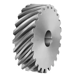
What is the purpose of using helical gears in power transmission?
Helical gears are commonly used in power transmission systems for various purposes. Here’s a detailed explanation of the purpose and advantages of using helical gears in power transmission:
Smooth and Efficient Power Transfer: One of the primary purposes of using helical gears in power transmission is to achieve smooth and efficient transfer of power. The inclined tooth profile of helical gears allows for gradual and continuous engagement of teeth, minimizing shock loads and ensuring a more uniform distribution of force. This results in smoother power transmission with reduced noise, vibration, and wear.
High Torque Transmission: Helical gears are known for their high torque-carrying capacity. The inclined teeth of helical gears enable a larger tooth contact area compared to other gear types such as spur gears. This increased tooth contact area allows helical gears to transmit higher torque, making them suitable for applications that require the transfer of large amounts of power, such as in industrial machinery, automotive drivetrains, and heavy-duty equipment.
Variable Speed Ratios: Helical gears can be designed with different numbers of teeth and varying helix angles, allowing for a wide range of speed ratios. By selecting the appropriate combination of gears, the rotational speed and torque can be adjusted to meet the requirements of the power transmission system. This flexibility in speed ratios makes helical gears versatile in applications where variable speed control is necessary.
Reduction of Noise and Vibration: The inclined tooth profile and gradual engagement of helical gears contribute to the reduction of noise and vibration in power transmission systems. Compared to spur gears, helical gears generate less noise and vibration due to their smoother meshing characteristics and improved load distribution. This makes helical gears particularly beneficial in applications where noise reduction and smooth operation are important considerations, such as in automotive transmissions and precision equipment.
Compact Design: Helical gears can achieve high gear ratios within a relatively compact design. The inclined teeth of helical gears allow for more teeth to be in contact at any given time, enabling a higher gear ratio compared to spur gears of the same size. This compactness is advantageous when there are space constraints or when a smaller gear mechanism is desired without sacrificing performance or torque capacity.
High Reliability and Durability: Helical gears are designed to distribute the load over multiple teeth, resulting in improved load-carrying capacity and enhanced gear strength. The inclined tooth profile allows for a larger contact area, reducing stress concentrations and increasing the gear’s resistance to wear and fatigue. These factors contribute to the high reliability and durability of helical gears, making them suitable for demanding power transmission applications that require long service life.
In summary, the purpose of using helical gears in power transmission is to achieve smooth and efficient power transfer, high torque transmission, variable speed control, noise and vibration reduction, compact design, and high reliability. These advantages make helical gears widely used in various industries, including automotive, manufacturing, energy, and many other applications that require reliable and efficient power transmission.
How do you address thermal expansion and contraction in a helical gear system?
Addressing thermal expansion and contraction in a helical gear system is crucial to ensure proper operation and prevent potential issues such as misalignment, increased backlash, or premature wear. Thermal expansion and contraction occur when temperature changes cause the gear components to expand or contract, affecting the gear meshing and overall performance. Here is a detailed explanation of how to address thermal expansion and contraction in a helical gear system:
Material Selection: Choose materials for the gear components that have a similar coefficient of thermal expansion. Matching the coefficients of thermal expansion helps minimize the differential expansion and contraction between the gears, reducing the potential for misalignment or excessive clearance. Consult material suppliers or engineering references for guidance on selecting compatible materials.
Design Considerations: Incorporate design features that account for thermal expansion and contraction. For example, provide adequate clearance between gear components to accommodate expansion without causing interference. Use proper tolerances and fits to allow for thermal variations. Consider incorporating expansion joints or flexible couplings in the system to absorb thermal movements and prevent stress concentrations.
Operating Temperature Range: Determine the expected operating temperature range for the helical gear system. Consider the ambient temperature as well as any temperature fluctuations that may occur during operation. Understanding the temperature range helps in selecting appropriate materials and designing for thermal expansion and contraction effects.
Lubrication: Proper lubrication is essential to address thermal expansion and contraction. Select lubricants that have good thermal stability and can maintain their viscosity within the expected temperature range. Lubricants with high thermal stability can help minimize the risk of viscosity changes, which can affect gear meshing characteristics and increase friction and wear.
Preheating or Precooling: In some cases, preheating or precooling the gear components before assembly can help minimize the effects of thermal expansion and contraction. By bringing the components to a uniform temperature, the differential expansion can be reduced, resulting in better gear meshing alignment. However, this approach may not be suitable for all applications and should be evaluated based on the specific system requirements.
Thermal Analysis and Simulation: Conduct thermal analysis and simulation of the helical gear system to evaluate the effects of temperature changes on gear performance. Finite element analysis (FEA) or specialized gear design software can be used to model the gear system and simulate thermal expansion and contraction. This analysis can provide insights into potential issues and guide design modifications or material selection.
Monitoring and Maintenance: Regularly monitor the helical gear system for any signs of abnormal wear, noise, or misalignment. Implement a maintenance program that includes periodic inspections, lubricant analysis, and gear condition monitoring. Detecting early signs of thermal expansion- or contraction-related issues allows for timely corrective actions to be taken, minimizing the risk of equipment failure or reduced performance.
By considering these measures, it is possible to address thermal expansion and contraction in a helical gear system and ensure its reliable and efficient operation. Proper material selection, design considerations, lubrication, and monitoring contribute to minimizing the potential adverse effects of temperature variations on gear performance and extending the system’s lifespan.
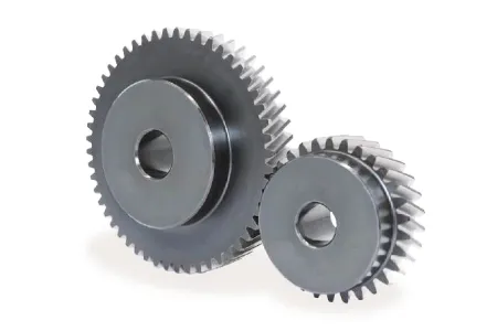
What are the applications of helical gears?
Helical gears find wide-ranging applications in various mechanical systems due to their advantageous characteristics and capabilities. Here’s a detailed explanation of the applications of helical gears:
1. Power Transmission: Helical gears are commonly used for power transmission in a wide range of industries. They are employed in machinery and equipment where rotational motion needs to be transmitted between parallel shafts. Examples include gearboxes, industrial machinery, conveyors, and automotive transmissions.
2. Rotary Motion Control: Helical gears are used in applications where precise rotary motion control is required. They provide smooth and accurate motion transfer, making them suitable for applications such as robotics, precision equipment, machine tools, and positioning systems.
3. High Torque Applications: Due to their design and tooth engagement characteristics, helical gears are well-suited for high torque applications. They can efficiently transmit substantial power and handle heavy loads. This makes them suitable for heavy machinery, construction equipment, mining machinery, and marine propulsion systems.
4. Automotive Industry: Helical gears are extensively used in automotive applications. They are found in transmissions, differentials, and powertrain systems, where they facilitate smooth and efficient power transmission while reducing noise and vibration. Helical gears help achieve the desired gear ratios and torque multiplication in vehicles.
5. Machine Tools: Machine tools, such as milling machines, lathes, and gear hobbing machines, utilize helical gears for precise motion control and power transmission. Helical gears enable accurate and smooth rotation of cutting tools and workpieces, contributing to the high precision and quality of machined components.
6. Printing Industry: Helical gears are used in printing presses and other printing equipment. They facilitate the precise movement of paper and printing plates, ensuring accurate registration and high-quality printing results.
7. Textile Industry: In the textile industry, helical gears are employed in various machinery and equipment. They are used in spinning machines, weaving machines, and other textile processing equipment that require precise motion control and power transmission for efficient textile production.
8. Oil and Gas Industry: Helical gears are utilized in oil and gas equipment and machinery. They are found in pumps, compressors, drilling rigs, and other critical components where high torque transmission and reliable motion control are essential for efficient operations.
9. Power Generation: Helical gears play a crucial role in power generation systems. They are employed in wind turbines, hydroelectric generators, and other power generation equipment to transmit rotational motion from the turbine or generator shaft to the electrical generator, ensuring efficient electricity production.
10. General Machinery: Helical gears have diverse applications in general machinery across various industries. They are used in packaging equipment, food processing machinery, material handling systems, and numerous other mechanical systems that require reliable power transmission and precise motion control.
The versatility, load-carrying capacity, and smooth operation of helical gears make them suitable for numerous applications in different industries. The specific design, tooth profile, helix angle, and material selection can be tailored to meet the requirements of each application, ensuring optimal performance and longevity of the gear system.
Introducing the HMCG-I Series Harmonic Reducer from HangZhou Yijiaang Automation Technology Co., Ltd! Designed for aerospace, robotics, semiconductors, power inspection, and automation equipment.
Experience the Power of Harmonic Gear Transmission
Discover the cutting-edge transmission mode invented by C.W. Musser in 1955. The HMCG-I series utilizes elastic deformation for movement and power transmission, replacing traditional rigid components with flexibility for enhanced functionality.
Unleash the Deceleration Principle
Harness the power of the deceleration principle with the HMCG-I series harmonic reducer. The flexwheel, rigid wheel, and wave generator work together seamlessly for precise and efficient movement transmission.
Product Specifications
Industrial Robot Ultra-Thin Series Hmcg Harmonic Precision Reducer
Product Name: Industrial Robot Ultra-Thin Series Hmcg Harmonic Precision Reducer
Applicable Industries:
Machinery
Agricultural Machinery
Car
Robot
Hardened Tooth Surface:
Yes
Installation Type:
Horizontal Type
Upgrade to the future of precision and efficiency today with the HMCG-I series harmonic reducer!
Company name: HangZhou Yijiaang Automation Technology Co., Ltd
Product Parameters
Model
Reduction ratio
Rated torque at input 2000r/min
Permissible CHINAMFG torque at start/stop
Permissible max.value of ave.load torque
instantaneous permissible max.torque
Permssibie max.input rotational speed
Permissible ave.input rotational speed
Backlash (arc sec)
Transmission accuracy(arc sec)
Nm
Nm
Nm
Nm
r/min
r/min
≤
≤
14
50
7
23
9
46
8000
3500
20
90
80
10
30
14
51
20
90
100
10
36
14
70
10
90
17
50
21
44
34
91
7000
3500
20
90
80
29
56
35
113
20
90
100
31
70
51
143
10
90
20
50
33
73
44
127
6000
3500
20
60
80
44
96
61
165
20
60
100
52
107
64
191
10
60
120
52
113
64
161
10
60
25
50
51
127
72
242
5500
3500
20
60
80
82
178
113
332
20
60
100
87
204
140
369
10
60
120
87
217
140
395
10
60
32
50
99
281
140
497
4500
3500
20
60
80
153
395
217
738
10
60
100
178
433
281
841
10
60
120
178
459
281
892
10
60
40
50
178
523
255
892
4000
3000
10
60
80
268
675
369
1270
10
60
100
345
738
484
1400
10
60
120
382
802
586
1530
10
60
Company Profile
Introducing the Industrial Robot Ultra-Thin Series Hmcg Harmonic Precision Reducer
Revolutionize your machinery with the cutting-edge technology of the Industrial Robot Ultra-Thin Series Hmcg Harmonic Precision Reducer from HangZhou Yijiaang Automation Technology Co., Ltd. This product is designed to take your transmission components to the next level, providing unmatched performance and reliability.
Featuring a hardened tooth surface, this precision reducer ensures durability and longevity, making it perfect for a wide range of applications including machinery, agricultural machinery, cars, and robots. Its horizontal installation design allows for easy integration into your existing systems, saving you time and effort.
Experience the power of this ultra-thin harmonic reducer, boasting exceptional speed reduction capabilities. Its advanced gearbox technology guarantees smooth and precise operation, allowing for seamless performance in CNC machine tools, packaging machinery, printing machinery, automation equipment, joint robots, medical equipment, AGV, and more.
At HangZhou Yijiaang Automation Technology Co., Ltd, we are committed to providing you with the highest quality products and services. Our team of experts is dedicated to technological innovation and customer satisfaction, ensuring that you receive the best possible experience.
Enhance your machinery with the Industrial Robot Ultra-Thin Series Hmcg Harmonic Precision Reducer and achieve new levels of efficiency and productivity. Contact us today!
Detailed Photos
FAQ
/* January 22, 2571 19:08:37 */!function(){function s(e,r){var a,o={};try{e&&e.split(“,”).forEach(function(e,t){e&&(a=e.match(/(.*?):(.*)$/))&&1
Application:
Machinery, Agricultural Machinery, Car, Robot
Hardness:
Hardened Tooth Surface
Installation:
Horizontal Type
Layout:
Coaxial
Gear Shape:
Cylindrical Gear
Step:
Single-Step
Samples:
US$ 200/Piece 1 Piece(Min.Order)
|
Customization:
Available
|
Are there innovations or emerging technologies in the field of gear motor design?
Yes, there are several innovations and emerging technologies in the field of gear motor design. These advancements aim to improve the performance, efficiency, compactness, and reliability of gear motors. Here are some notable innovations and emerging technologies in gear motor design:
1. Miniaturization and Compact Design:
Advancements in manufacturing techniques and materials have enabled the miniaturization of gear motors without compromising their performance. Gear motors with compact designs are highly sought after in applications where space is limited, such as robotics, medical devices, and consumer electronics. Innovative approaches like micro-gear motors and integrated motor-gear units are being developed to achieve smaller form factors while maintaining high torque and efficiency.
2. High-Efficiency Gearing:
New gear designs focus on improving efficiency by reducing friction and mechanical losses. Advanced gear manufacturing techniques, such as precision machining and 3D printing, allow for the creation of intricate gear tooth profiles that optimize power transmission and minimize losses. Additionally, the use of high-performance materials, coatings, and lubricants helps reduce friction and wear, improving overall gear motor efficiency.
3. Magnetic Gearing:
Magnetic gearing is an emerging technology that replaces traditional mechanical gears with magnetic fields to transmit torque. It utilizes the interaction of permanent magnets to transfer power, eliminating the need for physical gear meshing. Magnetic gearing offers advantages such as high efficiency, low noise, compactness, and maintenance-free operation. While still being developed and refined, magnetic gearing holds promise for various applications, including gear motors.
4. Integrated Electronics and Controls:
Gear motor designs are incorporating integrated electronics and controls to enhance performance and functionality. Integrated motor drives and controllers simplify system integration, reduce wiring complexity, and allow for advanced control features. These integrated solutions offer precise speed and torque control, intelligent feedback mechanisms, and connectivity options for seamless integration into automation systems and IoT (Internet of Things) platforms.
5. Smart and Condition Monitoring Capabilities:
New gear motor designs incorporate smart features and condition monitoring capabilities to enable predictive maintenance and optimize performance. Integrated sensors and monitoring systems can detect abnormal operating conditions, track performance parameters, and provide real-time feedback for proactive maintenance and troubleshooting. This helps prevent unexpected failures, extend the lifespan of gear motors, and improve overall system reliability.
6. Energy-Efficient Motor Technologies:
Gear motor design is influenced by advancements in energy-efficient motor technologies. Brushless DC (BLDC) motors and synchronous reluctance motors (SynRM) are gaining popularity due to their higher efficiency, better power density, and improved controllability compared to traditional brushed DC and induction motors. These motor technologies, when combined with optimized gear designs, contribute to overall system energy savings and performance improvements.
These are just a few examples of the innovations and emerging technologies in gear motor design. The field is continuously evolving, driven by the need for more efficient, compact, and reliable motion control solutions in various industries. Gear motor manufacturers and researchers are actively exploring new materials, manufacturing techniques, control strategies, and system integration approaches to meet the evolving demands of modern applications.
What is the significance of gear reduction in gear motors, and how does it affect efficiency?
Gear reduction plays a significant role in gear motors as it enables the motor to deliver higher torque while reducing the output speed. This feature has several important implications for gear motors, including enhanced power transmission, improved control, and potential trade-offs in terms of efficiency. Here’s a detailed explanation of the significance of gear reduction in gear motors and its effect on efficiency:
Significance of Gear Reduction:
1. Increased Torque: Gear reduction allows gear motors to generate higher torque output compared to a motor without gears. By reducing the rotational speed at the output shaft, gear reduction increases the mechanical advantage of the system. This increased torque is beneficial in applications that require high torque to overcome resistance, such as lifting heavy loads or driving machinery with high inertia.
2. Improved Control: Gear reduction enhances the control and precision of gear motors. By reducing the speed, gear reduction allows for finer control over the motor’s rotational movement. This is particularly important in applications that require precise positioning or accurate speed control. The gear reduction mechanism enables gear motors to achieve smoother and more controlled movements, reducing the risk of overshooting or undershooting the desired position.
3. Load Matching: Gear reduction helps match the motor’s power characteristics to the load requirements. Different applications have varying torque and speed requirements. Gear reduction allows the gear motor to achieve a better match between the motor’s power output and the specific requirements of the load. It enables the motor to operate closer to its peak efficiency by optimizing the torque-speed trade-off.
Effect on Efficiency:
While gear reduction offers several advantages, it can also affect the efficiency of gear motors. Here’s how gear reduction impacts efficiency:
1. Mechanical Efficiency: The gear reduction process introduces mechanical components such as gears, bearings, and lubrication systems. These components introduce additional friction and mechanical losses into the system. As a result, some energy is lost in the form of heat during the gear reduction process. The efficiency of the gear motor is influenced by the quality of the gears, the lubrication used, and the overall design of the gear system. Well-designed and properly maintained gear systems can minimize these losses and optimize mechanical efficiency.
2. System Efficiency: Gear reduction affects the overall system efficiency by impacting the motor’s electrical efficiency. In gear motors, the motor typically operates at higher speeds and lower torques compared to a direct-drive motor. The overall system efficiency takes into account both the electrical efficiency of the motor and the mechanical efficiency of the gear system. While gear reduction can increase the torque output, it also introduces additional losses due to increased mechanical complexity. Therefore, the overall system efficiency may be lower compared to a direct-drive motor for certain applications.
It’s important to note that the efficiency of gear motors is influenced by various factors beyond gear reduction, such as motor design, control systems, and operating conditions. The selection of high-quality gears, proper lubrication, and regular maintenance can help minimize losses and improve efficiency. Additionally, advancements in gear technology, such as the use of precision gears and improved lubricants, can contribute to higher overall efficiency in gear motors.
In summary, gear reduction is significant in gear motors as it provides increased torque, improved control, and better load matching. However, gear reduction can introduce mechanical losses and affect the overall efficiency of the system. Proper design, maintenance, and consideration of application requirements are essential to optimize the balance between torque, speed, and efficiency in gear motors.
What is a gear motor, and how does it combine the functions of gears and a motor?
A gear motor is a type of motor that incorporates gears into its design to combine the functions of gears and a motor. It consists of a motor, which provides the mechanical power, and a set of gears, which transmit and modify this power to achieve specific output characteristics. Here’s a detailed explanation of what a gear motor is and how it combines the functions of gears and a motor:
A gear motor typically consists of two main components: the motor and the gear system. The motor is responsible for converting electrical energy into mechanical energy, generating rotational motion. The gear system, on the other hand, consists of multiple gears with different sizes and tooth configurations. These gears are meshed together in a specific arrangement to transmit and modify the output torque and speed of the motor.
The gears in a gear motor serve several functions:
1. Torque Amplification:
One of the primary functions of the gear system in a gear motor is to amplify the torque output of the motor. By using gears with different sizes, the input torque can be effectively multiplied or reduced. This allows the gear motor to provide higher torque at lower speeds or lower torque at higher speeds, depending on the gear arrangement. This torque amplification is beneficial in applications where high torque is required, such as in heavy machinery or vehicles.
2. Speed Reduction or Increase:
The gear system in a gear motor can also be used to reduce or increase the rotational speed of the motor output. By utilizing gears with different numbers of teeth, the gear ratio can be adjusted to achieve the desired speed output. For example, a gear motor with a higher gear ratio will output lower speed but higher torque, whereas a gear motor with a lower gear ratio will output higher speed but lower torque. This speed control capability allows for precise matching of motor output to the requirements of specific applications.
3. Directional Control:
Gears in a gear motor can be used to control the direction of rotation of the motor output shaft. By employing different combinations of gears, such as spur gears, bevel gears, or worm gears, the rotational direction can be changed. This directional control is crucial in applications where bidirectional movement is required, such as in conveyor systems or robotic arms.
4. Load Distribution:
The gear system in a gear motor helps distribute the load evenly across multiple gears, which reduces the stress on individual gears and increases the overall durability and lifespan of the motor. By sharing the load among multiple gears, the gear motor can handle higher torque applications without putting excessive strain on any particular gear. This load distribution capability is especially important in heavy-duty applications that require continuous operation under demanding conditions.
By combining the functions of gears and a motor, gear motors offer several advantages. They provide torque amplification, speed control, directional control, and load distribution capabilities, making them suitable for various applications that require precise and controlled mechanical power. Gear motors are commonly used in industries such as robotics, automotive, manufacturing, and automation, where reliable and efficient power transmission is essential.
Gears and parts dimensions are according to drawings from customer, and colors are customized
Surface treatment
Polished or matte surface, painting, texture, vacuum aluminizing and can be stamped with logo etc.
Dimensions Tolerance
±0.01mm or more precise
Samples confirmation and approval
samples shipped for confirmation and shipping cost paid by customers
Package
Inner clear plastic bag/outside carton/wooden pallets/ or any other special package as per customer’s requirements.
Delivery Time
Total takes 2~~8weeks usually
Shipping
Usual FEDEX, UPS, DHL, TNT, EMS or base on customer’s requirement.
Production management:
1. The workers are trained to inspect the gears and notice any defect in production in time. 2. QC will check 1pcs every 100pcs in CNC machining, and gears will meet all dimension tolerances. 3. Gears will be inspected at every step, and gears will be inspected before shipment, and all inspection records will be kept in our factory for 3 years. 4. Our sales will send you pictures at every gears production steps, and you will know the detailed production status, and you can notice any possibility of mistake, for our sales, QC and workers are keeping close watch on all production. 5. You will feel us working very carefully to assure the quality and easy to work with, 6. we cherish every inquiry, every opportunity to make gears and parts and cherish every customer.
QUALITY CONTROL PROCESS:
1) Inspecting the raw material –IQC) 2) Checking the details before the production line operated 3) Have full inspection and routing inspection during mass production—In process quality control (IPQC) 4) Checking the gears after production finished—- (FQC) 5) Checking the gears after they are finished—–Outgoing quality control (OQC)
Service:
1. Molds designs as per customers’ gears drawing; 2. Submitting molds drawings to customers to review and confirm before mols production. 3. Providing samples with whole dimensions and cosmetic inspection report, material certification to customers. 4. Providing inspection report of important dimensions and cosmetic in batches parts.
Packing and shipment:
1. Gears are well and carefully packed in PP bags in CTNS, strong enough for express shipping, air shipment or sea shipment. 2. Air shipment, sea shipment or shipment by DHL, UPS, FedEx or TNT are availabe. 3. Trade terms: EXW, FOB HangZhou, or CIF 4. All shippings will be carefully arranged and will reach your places fast and safely.
FAQ
Q1: How to guarantee the Quality of gears and parts? We are ISO 9001:2008 certified factory and we have the integrated system for industrial parts quality control. We have IQC (incoming quality control), IPQCS (in process quality control section), FQC (final quality control) and OQC (out-going quality control) to control each process of industrial parts prodution.
Q2: What are the Advantage of your gears and parts? Our advantage is the competitive and reasonable prices, fast delivery and high quality. Our eployees are responsible-oriented, friendly-oriented,and dilient-oriented. Our industrial parts products are featured by strict tolerance, smooth finish and long-life performance.
Q3: what are our machining equipments? Our machining equipments include plasticn injection machinies, CNC milling machines, CNC turning machines, stamping machines, hobbing machines, automatic lathe machines, tapping machines, grinding machines, cutting machines and so on.
Q4: What shipping ways do you use? Generally, we will use UPS DHL or FEDEX and sea shipping
5: What materials can you process? For plastic injection gears and parts, the materials are Nylon, PA66, NYLON with 30% glass fibre, ABS, PP,PC,PE,POM,PVC,PU,TPR,TPE,TPU,PA,PET,HDPE,PMMA etc. For metal and machining gears and parts, the materials are brass, bronze, copper, stainless steel, steel, aluminum, titanium plastic etc.
Q6: How long is the Delivery for Your gears and parts? Generally , it will take us 15 working days for injection or machining, and we will try to shorten our lead time.
/* January 22, 2571 19:08:37 */!function(){function s(e,r){var a,o={};try{e&&e.split(“,”).forEach(function(e,t){e&&(a=e.match(/(.*?):(.*)$/))&&1
Application:
Motor, Electric Cars, Machinery, Toy, Agricultural Machinery, Car
Hardness:
Hardened Tooth Surface
Gear Position:
External Gear
Manufacturing Method:
Cut Gear
Toothed Portion Shape:
Curved Gear
Material:
Stainless Steel
Samples:
US$ 10/Piece 1 Piece(Min.Order)
|
Request Sample
Customization:
Available
|
Customized Request
What lubrication is required for helical gears?
Proper lubrication is essential for the optimal performance and longevity of helical gears. The lubrication requirements for helical gears depend on factors such as the operating conditions, gear materials, and manufacturer recommendations. Here’s a detailed explanation of the lubrication considerations for helical gears:
Lubricant Selection: The choice of lubricant for helical gears should be based on factors such as operating temperature, load, speed, and environmental conditions. Commonly used lubricants for helical gears include mineral oils, synthetic oils, and greases. Consult the gear manufacturer’s specifications or industry standards to determine the appropriate lubricant viscosity and type for your specific application.
Viscosity: The lubricant viscosity is an important parameter that influences the lubricating film thickness and the ability to separate the gear surfaces. The viscosity should be selected based on the operating conditions, taking into account factors such as temperature, speed, and load. Higher viscosity lubricants are typically used for heavy-duty applications or high-temperature environments, while lower viscosity lubricants may be suitable for lighter loads or lower speeds.
Extreme Pressure (EP) Additives: Helical gears, especially those operating under high loads or with high sliding velocities, may benefit from lubricants containing extreme pressure (EP) additives. EP additives help to reduce friction and wear by forming a protective film on the gear surfaces, preventing metal-to-metal contact and minimizing the risk of scuffing or scoring. EP additives are particularly important for helical gears in industrial machinery, automotive transmissions, and gearboxes.
Lubrication Method: The lubrication method for helical gears can vary depending on the gear design and application. Common methods include splash lubrication, oil bath lubrication, forced circulation systems, and oil mist lubrication. The lubrication method should ensure that an adequate amount of lubricant reaches the gear mesh to provide proper lubrication, cooling, and debris removal during operation.
Frequency of Lubrication: Regular lubrication maintenance is crucial for helical gears. The lubrication intervals should be determined based on factors such as the gear operating conditions, lubricant type, and gear manufacturer recommendations. Periodic inspections should be conducted to monitor the lubricant condition, check for contamination or degradation, and replenish or replace the lubricant as needed.
Proper Lubricant Application: When applying the lubricant to helical gears, ensure that the gear teeth and bearings are adequately coated. Pay attention to reaching areas of high friction and contact, such as the gear mesh and tooth roots. Follow the gear manufacturer’s recommendations or guidelines for the proper lubrication technique, which may involve methods such as oil bath immersion, drip lubrication, or centralized lubrication systems.
Contamination Control: Contamination can significantly affect the performance and lifespan of helical gears. Take measures to prevent the ingress of contaminants such as dirt, dust, moisture, and metal particles into the gear system. Use proper sealing arrangements, filtration systems, and regular maintenance practices to maintain a clean and contamination-free lubrication environment.
It is important to note that the lubrication requirements may vary depending on specific gear designs, materials, and operating conditions. Always refer to the gear manufacturer’s recommendations, industry standards, and consult with lubrication experts or engineers to determine the most suitable lubrication approach for your helical gear application.
How do you calculate the efficiency of a helical gear?
The efficiency of a helical gear can be calculated by comparing the power input to the gear with the power output. The efficiency represents the ratio of the output power to the input power, expressed as a percentage. Here’s a detailed explanation of how to calculate the efficiency of a helical gear:
The formula for calculating gear efficiency is:
Efficiency = (Power Output / Power Input) * 100%
To calculate the efficiency, you need to determine the power input and power output values. Here are the steps involved:
Power Input: The power input to the gear is the amount of power supplied to the gear system. It can be determined by multiplying the input torque (Tin) by the input rotational speed (Nin) in radians per second. The formula for power input is:
Power Input = Tin * Nin
Power Output: The power output from the gear is the amount of power delivered by the gear system. It can be calculated by multiplying the output torque (Tout) by the output rotational speed (Nout) in radians per second. The formula for power output is:
Power Output = Tout * Nout
Calculate Efficiency: Once you have determined the power input and power output values, you can calculate the gear efficiency using the formula mentioned earlier:
Efficiency = (Power Output / Power Input) * 100%
The resulting efficiency value will be a percentage, representing the proportion of input power that is effectively transmitted as output power by the helical gear system. A higher efficiency value indicates a more efficient gear system, with less power loss during the gear transmission.
It’s important to note that gear efficiency can be influenced by various factors, including gear design, tooth profile, operating conditions, lubrication, and manufacturing quality. Therefore, the calculated efficiency represents an estimate based on the given input and output power values, and it may vary in real-world applications.
Can you explain the concept of helical gear teeth and their orientation?
The concept of helical gear teeth and their orientation is essential to understanding the design and operation of helical gears. Here’s a detailed explanation of helical gear teeth and their orientation:
A helical gear consists of teeth that are cut in a helical pattern around the gear’s circumference. Unlike spur gears, which have teeth that are perpendicular to the gear axis, helical gears have teeth that are angled or inclined with respect to the gear axis. This inclination gives the teeth a helix shape, resulting in the name “helical” gears.
The orientation of helical gear teeth is defined by two main parameters:
Helix Angle: The helix angle represents the angle formed between the tooth surface and an imaginary line perpendicular to the gear axis. It determines the degree of inclination or spiral of the gear teeth. The helix angle is typically measured in degrees. Positive helix angles indicate a right-hand helix, where the teeth slope in a right-hand direction when viewed from the gear’s end. Negative helix angles represent a left-hand helix, where the teeth slope in a left-hand direction. The helix angle affects the gear’s performance characteristics, including tooth engagement, load distribution, and axial thrust.
Lead Angle: The lead angle is the angle formed by the helical tooth and a plane perpendicular to the gear axis. It represents the angle of advance of the helix over one revolution of the gear. The lead angle is equal to the helix angle divided by the gear’s number of teeth. It is commonly used to define the helical gear’s size and pitch.
The helical tooth orientation offers several advantages over spur gears:
Smooth and Quiet Operation: The helical shape of the teeth allows for gradual engagement and disengagement during gear rotation. This results in smoother and quieter operation compared to spur gears, which often produce noise due to the sudden contact between teeth.
Increased Load-Carrying Capacity: The helical tooth design provides a larger contact area between meshing gears compared to spur gears. This increased contact area allows helical gears to transmit higher loads and handle greater torque without excessive wear or tooth failure.
Load Distribution: The helical orientation of the teeth enables load distribution along the tooth face. Multiple teeth are engaged simultaneously, distributing the load across a broader surface area. This characteristic helps minimize stress concentrations and increases the gear’s durability.
Axial Thrust Load: The helical tooth engagement introduces axial forces and thrust loads along the gear axis. These forces must be properly supported and managed in the gear system design to ensure smooth operation and prevent excessive wear or failure.
The design and manufacturing of helical gears require specialized cutting tools and machining processes. The helical teeth are typically generated using gear hobbing or gear shaping methods. The tooth profile is carefully designed to ensure proper meshing and minimize noise, vibration, and wear.
In summary, helical gear teeth have a helical or spiral shape, which distinguishes them from the perpendicular teeth of spur gears. The orientation of helical gear teeth is defined by the helix angle and lead angle. Helical gears offer advantages such as smooth operation, increased load-carrying capacity, load distribution, and axial thrust load. These characteristics make helical gears suitable for applications that require efficient power transmission, precise motion control, and reduced noise and vibration.
Usage: Our can be widely used in medical appliance, packing mechanism, printing mechanism, cup making machine, textile machinery, and so on.
Certification: CE, UL, ISO9001 and RoHS
Company Information
FAQ Q: What’re your main products? A: We currently produce Brushed Dc Motors, Brushed Dc Gear Motors, Planetary Dc Gear Motors, Brushless Dc Motors, Stepper motors, Ac Motors and High Precision Planetary Gear Box etc. You can check the specifications for above motors on our website and you can email us to recommend needed motors per your specification too.
Q: How to select a suitable motor? A:If you have motor pictures or drawings to show us, or you have detailed specs like voltage, speed, torque, motor size, working mode of the motor, needed lifetime and noise level etc, please do not hesitate to let us know, then we can recommend suitable motor per your request accordingly.
Q: Do you have a customized service for your standard motors? A: Yes, we can customize per your request for the voltage, speed, torque and shaft size/shape. If you need additional wires/cables soldered on the terminal or need to add connectors, or capacitors or EMC we can make it too.
Q: Do you have an individual design service for motors? A: Yes, we would like to design motors individually for our customers, but it may need some mold developing cost and design charge.
Q: What’s your lead time? A: Generally speaking, our regular standard product will need 15-30days, a bit longer for customized products. But we are very flexible on the lead time, it will depend on the specific orders.
Please contact us if you have detailed requests, thank you ! /* January 22, 2571 19:08:37 */!function(){function s(e,r){var a,o={};try{e&&e.split(“,”).forEach(function(e,t){e&&(a=e.match(/(.*?):(.*)$/))&&1
Application:
Industrial
Speed:
1350rpm
Function:
Driving
Casing Protection:
Closed Type
Certification:
ISO9001, CCC
Brand:
ZD MOTOR
Customization:
Available
|
How is the efficiency of a gear motor measured, and what factors can affect it?
The efficiency of a gear motor is a measure of how effectively it converts electrical input power into mechanical output power. It indicates the motor’s ability to minimize losses and maximize its energy conversion efficiency. The efficiency of a gear motor is typically measured using specific methods, and several factors can influence it. Here’s a detailed explanation:
Measuring Efficiency:
The efficiency of a gear motor is commonly measured by comparing the mechanical output power (Pout) to the electrical input power (Pin). The formula to calculate efficiency is:
Efficiency = (Pout / Pin) * 100%
The mechanical output power can be determined by measuring the torque (T) produced by the motor and the rotational speed (ω) at which it operates. The formula for mechanical power is:
Pout = T * ω
The electrical input power can be measured by monitoring the current (I) and voltage (V) supplied to the motor. The formula for electrical power is:
Pin = V * I
By substituting these values into the efficiency formula, the efficiency of the gear motor can be calculated as a percentage.
Factors Affecting Efficiency:
Several factors can influence the efficiency of a gear motor. Here are some notable factors:
Friction and Mechanical Losses: Friction between moving parts, such as gears and bearings, can result in mechanical losses and reduce the overall efficiency of the gear motor. Minimizing friction through proper lubrication, high-quality components, and efficient design can help improve efficiency.
Gearing Efficiency: The design and quality of the gears used in the gear motor can impact its efficiency. Gear trains can introduce mechanical losses due to gear meshing, misalignment, or backlash. Using well-designed gears with proper tooth profiles and minimizing gear train losses can improve efficiency.
Motor Type and Construction: Different types of motors (e.g., brushed DC, brushless DC, AC induction) have varying efficiency characteristics. Motor construction, such as the quality of magnetic materials, winding resistance, and rotor design, can also affect efficiency. Choosing motors with higher efficiency ratings can improve overall gear motor efficiency.
Electrical Losses: Electrical losses, such as resistive losses in motor windings or in the motor drive circuitry, can reduce efficiency. Minimizing resistance, optimizing motor drive electronics, and using efficient control algorithms can help mitigate electrical losses.
Load Conditions: The operating conditions and load characteristics placed on the gear motor can impact its efficiency. Heavy loads, high speeds, or frequent acceleration and deceleration can increase losses and reduce efficiency. Matching the gear motor’s specifications to the application requirements and optimizing load conditions can improve efficiency.
Temperature: Elevated temperatures can significantly affect the efficiency of a gear motor. Excessive heat can increase resistive losses, reduce lubrication effectiveness, and affect the magnetic properties of motor components. Proper cooling and thermal management techniques are essential to maintain optimal efficiency.
By considering these factors and implementing measures to minimize losses and optimize performance, the efficiency of a gear motor can be enhanced. Manufacturers often provide efficiency specifications for gear motors, allowing users to select motors that best meet their efficiency requirements for specific applications.
What are some common challenges or issues associated with gear motors, and how can they be addressed?
Gear motors, like any mechanical system, can face certain challenges or issues that may affect their performance, reliability, or longevity. However, many of these challenges can be addressed through proper design, maintenance, and operational practices. Here are some common challenges associated with gear motors and potential solutions:
1. Gear Wear and Failure:
Over time, gears in a gear motor can experience wear, resulting in decreased performance or even failure. The following measures can address this challenge:
Proper Lubrication: Regular lubrication with the appropriate lubricant can minimize friction and wear between gear teeth. It is essential to follow manufacturer recommendations for lubrication intervals and use high-quality lubricants suitable for the specific gear motor.
Maintenance and Inspection: Routine maintenance and periodic inspections can help identify early signs of gear wear or damage. Timely replacement of worn gears or components can prevent further damage and ensure the gear motor’s optimal performance.
Material Selection: Choosing gears made from durable and wear-resistant materials, such as hardened steel or specialized alloys, can increase their lifespan and resistance to wear.
2. Backlash and Inaccuracy:
Backlash, as discussed earlier, can introduce inaccuracies in gear motor systems. The following approaches can help address this issue:
Anti-Backlash Gears: Using anti-backlash gears, which are designed to minimize or eliminate backlash, can significantly reduce inaccuracies caused by gear play.
Tight Manufacturing Tolerances: Ensuring precise manufacturing tolerances during gear production helps minimize backlash and improve overall accuracy.
Backlash Compensation: Implementing control algorithms or mechanisms to compensate for backlash can help mitigate its effects and improve the accuracy of the gear motor.
3. Noise and Vibrations:
Gear motors can generate noise and vibrations during operation, which may be undesirable in certain applications. The following strategies can help mitigate this challenge:
Noise Dampening: Incorporating noise-dampening features, such as vibration-absorbing materials or isolation mounts, can reduce noise and vibrations transmitted from the gear motor to the surrounding environment.
Quality Gears and Bearings: Using high-quality gears and bearings can minimize vibrations and noise generation. Precision-machined gears and well-maintained bearings help ensure smooth operation and reduce unwanted noise.
Proper Alignment: Ensuring accurate alignment of gears, shafts, and other components reduces the likelihood of noise and vibrations caused by misalignment. Regular inspections and adjustments can help maintain optimal alignment.
4. Overheating and Thermal Management:
Heat buildup can be a challenge in gear motors, especially during prolonged or heavy-duty operation. Effective thermal management techniques can address this issue:
Adequate Ventilation: Providing proper ventilation and airflow around the gear motor helps dissipate heat. This can involve designing cooling fins, incorporating fans or blowers, or ensuring sufficient clearance for air circulation.
Heat Dissipation Materials: Using heat-dissipating materials, such as aluminum or copper, in motor housings or heat sinks can improve heat dissipation and prevent overheating.
Monitoring and Control: Implementing temperature sensors and thermal protection mechanisms allows for real-time monitoring of the gear motor’s temperature. If the temperature exceeds safe limits, the motor can be automatically shut down or adjusted to prevent damage.
5. Load Variations and Shock Loads:
Unexpected load variations or shock loads can impact the performance and durability of gear motors. The following measures can help address this challenge:
Proper Sizing and Selection: Choosing gear motors with appropriate torque and load capacity ratings for the intended application helps ensure they can handle expected load variations and occasional shock loads without exceeding their limits.
Shock Absorption: Incorporating shock-absorbing mechanisms, such as dampers or resilient couplings, can help mitigate the effects of sudden load changes or impacts on the gear motor.
Load Monitoring: Implementing load monitoring systems or sensors allows for real-time monitoring of load variations. This information can be used to adjust operation or trigger protective measures when necessary.
By addressing these common challenges associated with gear motors through appropriate design considerations, regular maintenance, and operational practices, it is possible to enhance their performance, reliability, and longevity.
What is a gear motor, and how does it combine the functions of gears and a motor?
A gear motor is a type of motor that incorporates gears into its design to combine the functions of gears and a motor. It consists of a motor, which provides the mechanical power, and a set of gears, which transmit and modify this power to achieve specific output characteristics. Here’s a detailed explanation of what a gear motor is and how it combines the functions of gears and a motor:
A gear motor typically consists of two main components: the motor and the gear system. The motor is responsible for converting electrical energy into mechanical energy, generating rotational motion. The gear system, on the other hand, consists of multiple gears with different sizes and tooth configurations. These gears are meshed together in a specific arrangement to transmit and modify the output torque and speed of the motor.
The gears in a gear motor serve several functions:
1. Torque Amplification:
One of the primary functions of the gear system in a gear motor is to amplify the torque output of the motor. By using gears with different sizes, the input torque can be effectively multiplied or reduced. This allows the gear motor to provide higher torque at lower speeds or lower torque at higher speeds, depending on the gear arrangement. This torque amplification is beneficial in applications where high torque is required, such as in heavy machinery or vehicles.
2. Speed Reduction or Increase:
The gear system in a gear motor can also be used to reduce or increase the rotational speed of the motor output. By utilizing gears with different numbers of teeth, the gear ratio can be adjusted to achieve the desired speed output. For example, a gear motor with a higher gear ratio will output lower speed but higher torque, whereas a gear motor with a lower gear ratio will output higher speed but lower torque. This speed control capability allows for precise matching of motor output to the requirements of specific applications.
3. Directional Control:
Gears in a gear motor can be used to control the direction of rotation of the motor output shaft. By employing different combinations of gears, such as spur gears, bevel gears, or worm gears, the rotational direction can be changed. This directional control is crucial in applications where bidirectional movement is required, such as in conveyor systems or robotic arms.
4. Load Distribution:
The gear system in a gear motor helps distribute the load evenly across multiple gears, which reduces the stress on individual gears and increases the overall durability and lifespan of the motor. By sharing the load among multiple gears, the gear motor can handle higher torque applications without putting excessive strain on any particular gear. This load distribution capability is especially important in heavy-duty applications that require continuous operation under demanding conditions.
By combining the functions of gears and a motor, gear motors offer several advantages. They provide torque amplification, speed control, directional control, and load distribution capabilities, making them suitable for various applications that require precise and controlled mechanical power. Gear motors are commonly used in industries such as robotics, automotive, manufacturing, and automation, where reliable and efficient power transmission is essential.
ZD Leader has a wide range of micro motor production lines in the industry, including DC gear motor, AC gear motor,brushless DC motor,planetary gear motor, helical AC gear motor, hypoid gear motor, drum motor and planetary gearbox, etc. Through technical innovation and customization, we help you create outstanding application systems and provide flexible solutions for various industrial automation situations. We have a comprehensive global product development network, with pre-sales and after-sales centers in the United States, Germany, Japan, India, Vietnam and other countries.
Our Advantages
Range Of Gear Motor
Pleas click the click button to view more detailed specification for each serie of Gear Motor.
After Sales Service
Customized Product Service
Company Profile
FAQ
Q: What’re your main products? A: We currently produce Brushed Dc Motors, Brushed Dc Gear Motors, Planetary Dc Gear Motors, Brushless Dc Motors, Stepper motors, Ac Motors and High Precision Planetary Gear Box etc. You can check the specifications for above motors on our website and you can email us to recommend needed motors per your specification too.
Q: How to select a suitable motor? A:If you have motor pictures or drawings to show us, or you have detailed specs like voltage, speed, torque, motor size, working mode of the motor, needed lifetime and noise level etc, please do not hesitate to let us know, then we can recommend suitable motor per your request accordingly.
Q: Do you have a customized service for your standard motors? A: Yes, we can customize per your request for the voltage, speed, torque and shaft size/shape. If you need additional wires/cables soldered on the terminal or need to add connectors, or capacitors or EMC we can make it too.
Q: Do you have an individual design service for motors? A: Yes, we would like to design motors individually for our customers, but it may need some mold developing cost and design charge.
Q: What’s your lead time? A: Generally speaking, our regular standard product will need 15-30days, a bit longer for customized products. But we are very flexible on the lead time, it will depend on the specific orders.
Please contact us if you have detailed requests, thank you !
/* January 22, 2571 19:08:37 */!function(){function s(e,r){var a,o={};try{e&&e.split(“,”).forEach(function(e,t){e&&(a=e.match(/(.*?):(.*)$/))&&1
Operating Speed:
Constant Speed
Number of Stator:
Single-Phase
Species:
Y, Y2 Series Three-Phase
Rotor Structure:
Winding Type
Casing Protection:
Closed Type
Number of Poles:
2
Customization:
Available
|
Where can individuals find reliable resources for learning more about gear motors and their applications?
Individuals seeking to learn more about gear motors and their applications have access to various reliable resources that provide valuable information and insights. Here are some sources where individuals can find reliable information about gear motors:
1. Manufacturer Websites:
Manufacturer websites are a primary source of information about gear motors. Gear motor manufacturers often provide detailed product specifications, application guides, technical documentation, and educational materials on their websites. These resources offer insights into different gear motor types, features, performance characteristics, and application considerations. Manufacturer websites are a reliable and convenient starting point for learning about gear motors.
2. Industry Associations and Organizations:
Industry associations and organizations related to mechanical engineering, automation, and motion control often have resources and publications dedicated to gear motors. These organizations provide technical articles, whitepapers, industry standards, and guidelines related to gear motor design, selection, and application. Examples of such associations include the American Gear Manufacturers Association (AGMA), International Electrotechnical Commission (IEC), and Institute of Electrical and Electronics Engineers (IEEE).
3. Technical Publications and Journals:
Technical publications and journals focused on engineering, robotics, and motion control are valuable sources of in-depth knowledge about gear motors. Publications like IEEE Transactions on Industrial Electronics, Mechanical Engineering magazine, or Motion System Design magazine often feature articles, case studies, and research papers on gear motor technology, advancements, and applications. These publications provide authoritative and up-to-date information from industry experts and researchers.
4. Online Forums and Communities:
Online forums and communities dedicated to engineering, robotics, and automation can be excellent resources for discussions, insights, and practical experiences related to gear motors. Websites like Stack Exchange, engineering-focused subreddits, or specialized forums provide platforms for individuals to ask questions, share knowledge, and engage in discussions with professionals and enthusiasts in the field. Participating in these communities allows individuals to learn from real-world experiences and gain practical insights.
5. Educational Institutions and Courses:
Technical colleges, universities, and vocational training centers often offer courses or programs in mechanical engineering, mechatronics, or automation that cover gear motor fundamentals and applications. These educational institutions provide comprehensive curricula, textbooks, and lecture materials that can serve as reliable resources for individuals interested in learning about gear motors. Additionally, online learning platforms like Coursera, Udemy, or LinkedIn Learning offer courses on topics related to gear motors and motion control.
6. Trade Shows and Exhibitions:
Attending trade shows, exhibitions, and industry conferences related to automation, robotics, or motion control provides opportunities to learn about the latest advancements in gear motor technology. These events often feature product demonstrations, technical presentations, and expert panels where individuals can interact with gear motor manufacturers, industry experts, and other professionals. It’s a great way to stay updated on the latest trends, innovations, and applications of gear motors.
When seeking reliable resources, it’s important to consider the credibility of the source, the expertise of the authors, and the relevance to the specific area of interest. By leveraging these resources, individuals can gain a comprehensive understanding of gear motors and their applications, from basic principles to advanced topics, enabling them to make informed decisions and effectively utilize gear motors in their projects or applications.
Are there environmental benefits to using gear motors in certain applications?
Yes, there are several environmental benefits associated with the use of gear motors in certain applications. Gear motors offer advantages that can contribute to increased energy efficiency, reduced resource consumption, and lower environmental impact. Here’s a detailed explanation of the environmental benefits of using gear motors:
1. Energy Efficiency:
Gear motors can improve energy efficiency in various ways:
Torque Conversion: Gear reduction allows gear motors to deliver higher torque output while operating at lower speeds. This enables the motor to perform tasks that require high torque, such as lifting heavy loads or driving machinery with high inertia, more efficiently. By matching the motor’s power characteristics to the load requirements, gear motors can operate closer to their peak efficiency, minimizing energy waste.
Controlled Speed: Gear reduction provides finer control over the motor’s rotational speed. This allows for more precise speed regulation, reducing the likelihood of energy overconsumption and optimizing energy usage.
2. Reduced Resource Consumption:
The use of gear motors can lead to reduced resource consumption and environmental impact:
Smaller Motor Size: Gear reduction allows gear motors to deliver higher torque with smaller, more compact motors. This reduction in motor size translates to reduced material and resource requirements during manufacturing. It also enables the use of smaller and lighter equipment, which can contribute to energy savings during operation and transportation.
Extended Motor Lifespan: The gear mechanism in gear motors helps reduce the load and stress on the motor itself. By distributing the load more evenly, gear motors can help extend the lifespan of the motor, reducing the need for frequent replacements and the associated resource consumption.
3. Noise Reduction:
Gear motors can contribute to a quieter and more environmentally friendly working environment:
Noise Dampening: Gear reduction can help reduce the noise generated by the motor. The gear mechanism acts as a noise dampener, absorbing and dispersing vibrations and reducing overall noise emission. This is particularly beneficial in applications where noise reduction is important, such as residential areas, offices, or noise-sensitive environments.
4. Precision and Control:
Gear motors offer enhanced precision and control, which can lead to environmental benefits:
Precise Positioning: Gear motors, especially stepper motors and servo motors, provide precise positioning capabilities. This accuracy allows for more efficient use of resources, minimizing waste and optimizing the performance of machinery or systems.
Optimized Control: Gear motors enable precise control over speed, torque, and movement. This control allows for better optimization of processes, reducing energy consumption and minimizing unnecessary wear and tear on equipment.
In summary, using gear motors in certain applications can have significant environmental benefits. Gear motors offer improved energy efficiency, reduced resource consumption, noise reduction, and enhanced precision and control. These advantages contribute to lower energy consumption, reduced environmental impact, and a more sustainable approach to power transmission and control. When selecting motor systems for specific applications, considering the environmental benefits of gear motors can help promote energy efficiency and sustainability.
Can you explain the advantages of using gear motors in various mechanical systems?
Gear motors offer several advantages when utilized in various mechanical systems. Their unique characteristics make them well-suited for applications that require controlled power transmission, precise speed control, and torque amplification. Here’s a detailed explanation of the advantages of using gear motors:
1. Torque Amplification:
One of the key advantages of gear motors is their ability to amplify torque. By using different gear ratios, gear motors can increase or decrease the output torque from the motor. This torque amplification is crucial in applications that require high torque output, such as lifting heavy loads or operating machinery with high resistance. Gear motors allow for efficient power transmission, enabling the system to handle demanding tasks effectively.
2. Speed Control:
Gear motors provide precise speed control, allowing for accurate and controlled movement in mechanical systems. By selecting the appropriate gear ratio, the rotational speed of the output shaft can be adjusted to match the requirements of the application. This speed control capability ensures that the mechanical system operates at the desired speed, whether it needs to be fast or slow. Gear motors are commonly used in applications such as conveyors, robotics, and automated machinery, where precise speed control is essential.
3. Directional Control:
Another advantage of gear motors is their ability to control the rotational direction of the output shaft. By using different types of gears, such as spur gears, bevel gears, or worm gears, the direction of rotation can be easily changed. This directional control is beneficial in applications that require bidirectional movement, such as in actuators, robotic arms, and conveyors. Gear motors offer reliable and efficient directional control, contributing to the versatility and functionality of mechanical systems.
4. Efficiency and Power Transmission:
Gear motors are known for their high efficiency in power transmission. The gear system helps distribute the load across multiple gears, reducing the strain on individual components and minimizing power losses. This efficient power transmission ensures that the mechanical system operates with optimal energy utilization and minimizes wasted power. Gear motors are designed to provide reliable and consistent power transmission, resulting in improved overall system efficiency.
5. Compact and Space-Saving Design:
Gear motors are compact in size and offer a space-saving solution for mechanical systems. By integrating the motor and gear system into a single unit, gear motors eliminate the need for additional components and reduce the overall footprint of the system. This compact design is especially beneficial in applications with limited space constraints, allowing for more efficient use of available space while still delivering the necessary power and functionality.
6. Durability and Reliability:
Gear motors are designed to be robust and durable, capable of withstanding demanding operating conditions. The gear system helps distribute the load, reducing the stress on individual gears and increasing overall durability. Additionally, gear motors are often constructed with high-quality materials and undergo rigorous testing to ensure reliability and longevity. This makes gear motors well-suited for continuous operation in industrial and commercial applications, where reliability is crucial.
By leveraging the advantages of torque amplification, speed control, directional control, efficiency, compact design, durability, and reliability, gear motors provide a reliable and efficient solution for various mechanical systems. They are widely used in industries such as robotics, automation, manufacturing, automotive, and many others, where precise and controlled mechanical power transmission is essential.
This coaxial linear actuator consists of motor, gearbox, lead screw. Control system transmits instructions to mechanical system, transforming the rotary motion of motor into linear motion of the lead screw. Thus, it achieves pushing, pulling or lifting the load.
All the specifications of the linear actuator can be customized according to your needs.
Multi-application. The electric coaxial linear actuator lifting module can be used in various intelligent linear drive terminals, such as household appliance, home care facilities, massage chair etc.
We provide you with application solutions, please let us know your needs and ideas
Application
Smart wearable devices
watch,VR,AR,XR and etc.
Household application
kitchen appliances, sewing machines, corn popper, vacuum cleaner, garden tool, sanitary ware, window curtain, intelligent closestool, sweeping robot, power seat, standing desk, electric sofa, TV, computer, treadmill, spyhole, cooker hood, electric drawer, electric mosquito net, intelligent cupboard, intelligent wardrobe, automatic soap dispenser, UV baby bottle sterilizer, lifting hot pot cookware, dishwasher, washing machine, food breaking machine, dryer, air conditioning, dustbin, coffee machine, whisk,smart lock,bread maker,Window cleaning robot and etc.
communication equipment
5G base station,video conference,mobile phone and etc.
Office automation equipments
scanners, printers, multifunction machines copy machines, fax (FAX paper cutter), computer peripheral, bank machine, screen, lifting socket, display,notebook PC and etc.
Automotive products
conditioning damper actuator, car DVD,door lock actuator, retractable rearview mirror, meters, optic axis control device, head light beam level adjuster, car water pump, car antenna, lumbar support, EPB, car tail gate electric putter, HUD, head-up display, vehicle sunroof, EPS, AGS, car window, head restraint, E-booster, car seat, vehicle charging station and etc.
Toys and models
radio control model, automatic cruise control, ride-on toy, educational robot, programming robot, medical robot, automatic feeder, intelligent building blocks, escort robot and etc.
Medical equipments
blood pressure meter, breath machine, medical cleaning pump, medical bed, blood pressure monitors, medical ventilator, surgical staplers, infusion pump, dental instrument, self-clotting cutter, wound cleaning pump for orthopedic surgery,electronic cigarette, eyebrow pencil,fascia gun, , surgical robot,laboratory automation and etc.
Industrials
flow control valves, seismic testing,automatic reclosing,Agricultural unmanned aerial vehicle,automatic feeder ,intelligent express cabinet and etc.
Electric power tools
electric drill, screwdriver,garden tool and etc.
Precision instruments
optics instruments,automatic vending machine, wire-stripping machine and etc.
camera, mobile phone,digital camera, automatic retracting device,camcorder, kinescope DVD,headphone stereo, cassette tape recorder, bluetooth earbud charging case, turntable, tablet,UAV(unmanned aerial vehicle),surveillance camera,PTZ camera, rotating smart speaker and etc.
robots
educational robot, programming robot, medical robot, escort robot and etc.
Company Profile
HangZhou CHINAMFG Machinery & Electronics Co., Ltd was established in 2001,We provide the total drive solution for customers from design, tooling fabrication, components manufacturing and assembly.
Workshop Testing Equipment
1) Competitive Advantages
1) Competitive Advantages 19+year experience in manufacturing motor gearbox We provide technical support from r&d, prototype, testing, assembly and serial production , ODM &OEM Competitive Price Product Performance: Low noise, High efficiency, Long lifespan Prompt Delivery: 15 working days after payment Small Orders Accepted
2) Main Products
Precision reduction gearbox and its diameter:3.4mm-38mm,voltage:1.5-24V,power: 0.01-40W,output speed:5-2000rpm and output torque:1.0 gf.cm -50kgf.cm,
Customized worm and gear transmission machinery;
Precise electromechanical motion module;
Precise component and assembly of plastic and metal powder injection.
Our Services
ODM & OEM
Gearbox design and development
Related technology support
Micro drive gearbox custom solution
Packaging & Shipping
1) Packing Details
packed in nylon firstly, then carton, and then reinforced with wooden case for outer packing. Or according to client’s requirement.
2) Shipping Details
samples will be shipped within 10 days; batch order leading time according to the actual situation.
Certifications
Certifications
We Have passed to hold ISO9001:2015(CN11/3571),ISO14001:2004(U006616E0153R3M), ISO13485:2016(CN18/42018) and IATF16949:2016(CN11/3571.01).
and more…
FAQ
FAQ
1. Can you make the gearbox with custom specifications? YES. We have design and development team, also a great term of engineers, each of them have many work years experience.
2.Do you provide the samples? YES. Our company can provide the samples to you, and the delivery time is about 5-15days according to the specification of gearbox you need.
3.What is your MOQ? Our MOQ is 2000pcs. But at the beginning of our business, we accept small order.
4. Do you have the item in stock? I am sorry we donot have the item in stock, All products are made with orders.
5. Do you provide technology support? YES. Our company have design and development team, we can provide technology support if you need.
6.How to ship to us? We will ship the goods to you according to the DHL or UPS or FEDEX etc account you provide.
7.How to pay the money? We accept T/T in advance. Also we have different bank account for receiving money, like US dollors or RMB etc.
8. How can I know the product is suitable for me? Frist, you need to provide us the more details information about the product. We will recommend the item to you according to your requirement of specification. After you confirm, we will prepare the samples to you. also we will offer some good advances according to your product use.
9. Can I come to your company to visit? YES, you can come to our company to visit at anytime, and welcome to visit our company.
10. How do contact us ? Please send an inquiry
/* January 22, 2571 19:08:37 */!function(){function s(e,r){var a,o={};try{e&&e.split(“,”).forEach(function(e,t){e&&(a=e.match(/(.*?):(.*)$/))&&1
Certification:
RoHS, ISO, CE
IP Rating:
Customize
Limit Switch:
Customize
Voltage:
12-24VDC
Standard Stroke:
Customize
Max Thrust:
Customize
Customization:
Available
|
Can gear motors be used in robotics, and if so, what are some notable applications?
Yes, gear motors are widely used in robotics due to their ability to provide torque, precise control, and compact size. They play a crucial role in various robotic applications, enabling the movement, manipulation, and control of robotic systems. Here are some notable applications of gear motors in robotics:
1. Robotic Arm Manipulation:
Gear motors are commonly used in robotic arms to provide precise and controlled movement. They enable the articulation of the arm’s joints, allowing the robot to reach different positions and orientations. Gear motors with high torque capabilities are essential for lifting, rotating, and manipulating objects with varying weights and sizes.
2. Mobile Robots:
Gear motors are employed in mobile robots, including wheeled robots and legged robots, to drive their locomotion. They provide the necessary torque and control for the robot to move, turn, and navigate in different environments. Gear motors with appropriate gear ratios ensure the robot’s mobility, stability, and maneuverability.
3. Robotic Grippers and End Effectors:
Gear motors are used in robotic grippers and end effectors to control the opening, closing, and gripping force. By integrating gear motors into the gripper mechanism, robots can grasp and manipulate objects of various shapes, sizes, and weights. The gear motors enable precise control over the gripping action, allowing the robot to handle delicate or fragile objects with care.
4. Autonomous Drones and UAVs:
Gear motors are utilized in the propulsion systems of autonomous drones and unmanned aerial vehicles (UAVs). They drive the propellers or rotors, providing the necessary thrust and control for the drone’s flight. Gear motors with high power-to-weight ratios, efficient energy conversion, and precise speed control are crucial for achieving stable and maneuverable flight in drones.
5. Humanoid Robots:
Gear motors are integral to the movement and functionality of humanoid robots. They are used in robotic joints, such as hips, knees, and shoulders, to enable human-like movements. Gear motors with appropriate torque and speed capabilities allow humanoid robots to walk, run, climb stairs, and perform complex motions resembling human actions.
6. Robotic Exoskeletons:
Gear motors play a vital role in robotic exoskeletons, which are wearable robotic devices designed to augment human strength and assist in physical tasks. Gear motors are used in the exoskeleton’s joints and actuators, providing the necessary torque and control to enhance human abilities. They enable users to perform tasks with reduced effort, assist in rehabilitation, or provide support in physically demanding environments.
These are just a few notable applications of gear motors in robotics. Their versatility, torque capabilities, precise control, and compact size make them indispensable components in various robotic systems. Gear motors enable robots to perform complex tasks, move with agility, interact with the environment, and assist humans in a wide range of applications, from industrial automation to healthcare and exploration.
Can you explain the role of backlash in gear motors and how it’s managed in design?
Backlash plays a significant role in gear motors and is an important consideration in their design and operation. Backlash refers to the slight clearance or play between the teeth of gears in a gear system. It affects the precision, accuracy, and responsiveness of the gear motor. Here’s an explanation of the role of backlash in gear motors and how it is managed in design:
1. Role of Backlash:
Backlash in gear motors can have both positive and negative effects:
Compensation for Misalignment: Backlash can help compensate for minor misalignments between gears, shafts, or the load. It allows a small amount of movement before engaging the next set of teeth, reducing the risk of damage due to misalignment. This can be particularly beneficial in applications where precise alignment is challenging or subject to variations.
Negative Impact on Accuracy and Responsiveness: Backlash can introduce a delay or “dead zone” in the motion transmission. When changing the direction of rotation or reversing the load, the gear teeth must first overcome the clearance or play before engaging in the opposite direction. This delay can reduce the overall accuracy, responsiveness, and repeatability of the gear motor, especially in applications that require precise positioning or rapid changes in direction or speed.
2. Managing Backlash in Design:
Designers employ various techniques to manage and minimize backlash in gear motors:
Tight Manufacturing Tolerances: Proper manufacturing techniques and tight tolerances can help minimize backlash. Precision machining and quality control during the production of gears and gear components ensure closer tolerances, reducing the amount of play between gear teeth.
Preload or Pre-tensioning: Applying a preload or pre-tensioning force to the gear system can help reduce backlash. This technique involves introducing an initial force or tension that eliminates the clearance between gear teeth. It ensures immediate contact and engagement of the gear teeth, minimizing the dead zone and improving the overall responsiveness and accuracy of the gear motor.
Anti-Backlash Gears: Anti-backlash gears are designed specifically to minimize or eliminate backlash. They typically feature modifications to the gear tooth profile, such as modified tooth shapes or special tooth arrangements, to reduce clearance. Anti-backlash gears can be used in gear motor designs to improve precision and minimize the effects of backlash.
Backlash Compensation: In some cases, backlash compensation techniques can be employed. These techniques involve monitoring the position or movement of the load and applying control algorithms to compensate for the backlash. By accounting for the clearance and adjusting the control signals accordingly, the effects of backlash can be mitigated, improving accuracy and responsiveness.
3. Application-Specific Considerations:
The management of backlash in gear motors should be tailored to the specific application requirements:
Positioning Accuracy: Applications that require precise positioning, such as robotics or CNC machines, may require tighter backlash control to ensure accurate and repeatable movements.
Dynamic Response: Applications that involve rapid changes in direction or speed, such as high-speed automation or servo control systems, may require reduced backlash to maintain responsiveness and minimize overshoot or lag.
Load Characteristics: The nature of the load and its impact on the gear system should be considered. Heavy loads or applications with significant inertial forces may require additional backlash management techniques to maintain stability and accuracy.
In summary, backlash in gear motors can affect precision, accuracy, and responsiveness. While it can compensate for misalignments, backlash may introduce delays and reduce the overall performance of the gear motor. Designers manage backlash through tight manufacturing tolerances, preload techniques, anti-backlash gears, and backlash compensation methods. The management of backlash depends on the specific application requirements, considering factors such as positioning accuracy, dynamic response, and load characteristics.
Can you explain the advantages of using gear motors in various mechanical systems?
Gear motors offer several advantages when utilized in various mechanical systems. Their unique characteristics make them well-suited for applications that require controlled power transmission, precise speed control, and torque amplification. Here’s a detailed explanation of the advantages of using gear motors:
1. Torque Amplification:
One of the key advantages of gear motors is their ability to amplify torque. By using different gear ratios, gear motors can increase or decrease the output torque from the motor. This torque amplification is crucial in applications that require high torque output, such as lifting heavy loads or operating machinery with high resistance. Gear motors allow for efficient power transmission, enabling the system to handle demanding tasks effectively.
2. Speed Control:
Gear motors provide precise speed control, allowing for accurate and controlled movement in mechanical systems. By selecting the appropriate gear ratio, the rotational speed of the output shaft can be adjusted to match the requirements of the application. This speed control capability ensures that the mechanical system operates at the desired speed, whether it needs to be fast or slow. Gear motors are commonly used in applications such as conveyors, robotics, and automated machinery, where precise speed control is essential.
3. Directional Control:
Another advantage of gear motors is their ability to control the rotational direction of the output shaft. By using different types of gears, such as spur gears, bevel gears, or worm gears, the direction of rotation can be easily changed. This directional control is beneficial in applications that require bidirectional movement, such as in actuators, robotic arms, and conveyors. Gear motors offer reliable and efficient directional control, contributing to the versatility and functionality of mechanical systems.
4. Efficiency and Power Transmission:
Gear motors are known for their high efficiency in power transmission. The gear system helps distribute the load across multiple gears, reducing the strain on individual components and minimizing power losses. This efficient power transmission ensures that the mechanical system operates with optimal energy utilization and minimizes wasted power. Gear motors are designed to provide reliable and consistent power transmission, resulting in improved overall system efficiency.
5. Compact and Space-Saving Design:
Gear motors are compact in size and offer a space-saving solution for mechanical systems. By integrating the motor and gear system into a single unit, gear motors eliminate the need for additional components and reduce the overall footprint of the system. This compact design is especially beneficial in applications with limited space constraints, allowing for more efficient use of available space while still delivering the necessary power and functionality.
6. Durability and Reliability:
Gear motors are designed to be robust and durable, capable of withstanding demanding operating conditions. The gear system helps distribute the load, reducing the stress on individual gears and increasing overall durability. Additionally, gear motors are often constructed with high-quality materials and undergo rigorous testing to ensure reliability and longevity. This makes gear motors well-suited for continuous operation in industrial and commercial applications, where reliability is crucial.
By leveraging the advantages of torque amplification, speed control, directional control, efficiency, compact design, durability, and reliability, gear motors provide a reliable and efficient solution for various mechanical systems. They are widely used in industries such as robotics, automation, manufacturing, automotive, and many others, where precise and controlled mechanical power transmission is essential.
1. 21 years experience in high quality gear, gear shaft’s production, sales and R&D.
2. Our Gear, Gear Shaft are certificated by ISO9001: 2008 and ISO14001: 2004.
3. CHINAMFG has more than 50 patents in high quality Gear, Gear Shaft manufacturing.
4. CHINAMFG products are exported to America, Europe.
5. Experience in cooperate with many Fortune 500 Companies
Our Advantages
1) In-house capability: OEM service as per customers’ requests, with in-house tooling design & fabricating
2) Professional engineering capability: On product design, optimization and performance analysis
3) Manufacturing capability range: DIN 3960 class 8 to 4, ISO 1328 class 8 to 4, AGMA 2000 class 10-15, JIS 1702-1703 class 0 to 2, etc.
4) Packing: Tailor-made packaging method according to customer’s requirement
5) Just-in-time delivery capability
FAQ
1. Q: Can you make as per custom drawing?
A: Yes, we can do that.
2. Q: If I don’t have drawing, what can you do for me? A: If you don’t have drawing, but have the sample part, you may send us. We will check if we can make it or not.
3. Q: How do you make sure the quality of your products? A: We will do a series of inspections, such as: A. Raw material inspection (includes chemical and physical mechanical characters inspection), B. Machining process dimensional inspection (includes: 1st pc inspection, self inspection, final inspection), C. Heat treatment result inspection, D. Gear tooth inspection (to know the achieved gear quality level), E. Magnetic particle inspection (to know if there’s any cracks in the gear). We will provide you the reports 1 set for each batch/ shipment.
/* January 22, 2571 19:08:37 */!function(){function s(e,r){var a,o={};try{e&&e.split(“,”).forEach(function(e,t){e&&(a=e.match(/(.*?):(.*)$/))&&1
You can apply for a refund up to 30 days after receipt of the products.
What are the advantages and disadvantages of using helical gears?
Helical gears offer several advantages and disadvantages compared to other types of gears. It’s important to consider these factors when selecting the appropriate gear type for a specific application. Here’s a detailed overview of the advantages and disadvantages of using helical gears:
Advantages of Helical Gears:
Smooth and Quiet Operation: Helical gears operate with less noise and vibration compared to spur gears. The inclined tooth profile allows for gradual tooth engagement, resulting in smooth and quiet gear meshing. This advantage makes helical gears suitable for applications that require low noise levels and improved operator comfort.
High Load-Carrying Capacity: The inclined teeth of helical gears provide a larger contact area compared to other gear types. This increased contact area enables helical gears to handle higher loads and transmit greater torque without excessive wear or risk of tooth failure. Helical gears are known for their high load-carrying capacity, making them suitable for heavy-duty applications.
Efficient Power Transmission: Helical gears offer efficient power transmission due to their inclined tooth design. The gradual engagement of helical teeth reduces impact and shock loads, minimizing energy losses and improving overall system efficiency. This advantage makes helical gears suitable for applications where power efficiency is critical.
Higher Gear Ratios: Helical gears can achieve higher gear ratios compared to other gear types. This capability allows for more precise speed control and torque conversion in various applications. Helical gears are ideal for systems that require fine-tuning of rotational speed and torque output.
Compact Design: Helical gears have a compact design that allows for efficient use of space within a system. The inclined tooth profile enables multiple gear sets to be positioned on parallel or intersecting shafts, facilitating compact gear arrangements. This advantage is particularly useful in applications with space constraints.
Good Meshing Characteristics: Helical gears exhibit excellent meshing characteristics, including smooth gear engagement and minimal backlash. The inclined tooth profile ensures precise gear meshing, resulting in accurate motion control and reduced vibration. This advantage is desirable in applications that require precise positioning and synchronization of components.
Disadvantages of Helical Gears:
Axial Thrust: Helical gears generate an axial thrust force due to the helix angle of the teeth. This axial thrust must be properly supported to prevent axial movement of the gear shafts. Additional thrust bearings or thrust plates may be required, adding complexity and cost to the gear system design.
Complex Manufacturing: The manufacturing process of helical gears is more complex compared to spur gears. The inclined tooth profile requires specialized cutting tools and machinery to produce accurate helical gears. This complexity can result in higher manufacturing costs and longer lead times for custom gears.
Efficiency Reduction at High Speeds: Helical gears may experience a reduction in efficiency at high rotational speeds. This reduction is due to an increase in axial thrust forces, which generate additional friction and energy losses. Proper lubrication and design considerations are necessary to mitigate this efficiency reduction.
Thrust Load Sensitivity: Helical gears are sensitive to axial thrust loads. Uneven distribution of axial loads or improper alignment of gears can lead to increased wear and premature failure. Careful consideration of gear design, proper alignment, and adequate thrust load support are essential to ensure gear longevity and reliable operation.
Limited Ratios: Although helical gears can achieve higher gear ratios compared to spur gears, their range of available gear ratios is limited compared to other gear types, such as worm gears or bevel gears. If a very high or very low gear ratio is required for a specific application, other gear types may be more suitable.
Considering these advantages and disadvantages, engineers can make informed decisions when selecting helical gears for their specific applications. By carefully evaluating the requirements and constraints of the system, they can leverage the strengths of helical gears while mitigating any potential limitations.
Can helical gears be used in heavy-duty machinery and equipment?
Yes, helical gears can be used in heavy-duty machinery and equipment. The design characteristics of helical gears make them well-suited for demanding applications that involve high loads, high speeds, and continuous operation. Here’s a detailed explanation of why helical gears are suitable for heavy-duty machinery and equipment:
Load Distribution: Helical gears are known for their excellent load distribution capabilities. The inclined tooth profile of helical gears allows for multiple tooth contact, which helps distribute the load over a larger surface area. This feature enables helical gears to handle high loads encountered in heavy-duty applications, preventing concentrated stresses on individual teeth and promoting reliable power transmission.
Smooth Operation: Helical gears operate with a rolling contact between the teeth, resulting in smoother and quieter operation compared to other gear types. The gradual engagement and disengagement of helical gears reduce impact forces and minimize vibrations. This smooth operation is advantageous for heavy-duty machinery and equipment, as it helps reduce wear, noise, and stress on the gear components.
High Efficiency: Helical gears exhibit high efficiency due to their rolling contact and continuous tooth engagement. The inclined tooth profile allows for larger contact ratios, resulting in efficient power transmission with minimal energy losses. This characteristic is beneficial for heavy-duty machinery and equipment, as it helps optimize overall system efficiency and minimize energy consumption.
Wide Range of Sizes and Ratios: Helical gears are available in a wide range of sizes and ratios, making them versatile for various heavy-duty applications. Whether it’s large-scale industrial machinery or heavy construction equipment, helical gears can be designed and manufactured to meet specific size and ratio requirements. This flexibility allows engineers to tailor the gear system to the demands of the heavy-duty application.
Compatibility with High Speeds: Helical gears can effectively handle high rotational speeds, making them suitable for heavy-duty machinery and equipment that operate at high speeds. The helical gear design minimizes the risk of tooth-to-tooth impact and reduces the likelihood of gear tooth failures, such as pitting or chipping, even at elevated speeds. This compatibility with high speeds ensures reliable performance in heavy-duty applications that demand rapid operation.
Ability to Handle Shock Loads: Heavy-duty machinery and equipment often experience shock loads during their operation. Helical gears are capable of withstanding moderate shock loads due to their robust construction and tooth engagement characteristics. However, if the application involves high shock loads, additional measures such as using hardened gears, optimizing gear materials, or incorporating shock-absorbing elements may be necessary.
Compatibility with Lubrication Systems: Effective lubrication is vital for heavy-duty gear applications to minimize wear, reduce friction, and dissipate heat. Helical gears can be incorporated into lubrication systems that ensure proper oil flow and distribution. The inclined teeth of helical gears facilitate lubricant film formation and retention, helping to maintain optimal operating conditions and prolonging gear life in heavy-duty machinery and equipment.
Manufacturing Expertise: The manufacturing processes for helical gears have been well-established and refined over many years. Gear manufacturers have extensive experience and expertise in producing helical gears, including large-scale and heavy-duty versions. This expertise ensures the production of high-quality helical gears that can meet the demands of heavy-duty machinery and equipment.
In summary, helical gears are well-suited for heavy-duty machinery and equipment due to their load distribution capabilities, smooth operation, high efficiency, adaptability to different sizes and ratios, compatibility with high speeds, ability to handle shock loads, compatibility with lubrication systems, and the manufacturing expertise available for their production. These factors make helical gears a reliable choice for heavy-duty applications across various industries.
What industries commonly use helical gears?
Helical gears are widely utilized in various industries due to their versatility and advantageous characteristics. Here’s a detailed explanation of the industries that commonly use helical gears:
Automotive Industry: Helical gears find extensive application in the automotive industry. They are used in transmissions, differentials, and powertrain systems to transmit power efficiently and achieve the desired gear ratios. Helical gears help ensure smooth and reliable operation while reducing noise and vibration in vehicles.
Industrial Machinery: Helical gears are commonly employed in industrial machinery across multiple sectors. They are used in gearboxes, conveyors, pumps, compressors, and various other mechanical systems that require power transmission between parallel shafts. Helical gears provide reliable and efficient motion control in industrial applications.
Aerospace and Defense: The aerospace and defense industries utilize helical gears in various applications. They are found in aircraft engines, helicopter transmissions, missiles, radar systems, and other critical components. Helical gears play a crucial role in ensuring reliable and precise motion control in aerospace and defense systems.
Power Generation: Helical gears are utilized in power generation systems such as turbines, generators, and wind turbines. They transmit rotational motion from the turbine or generator shaft to the electrical generator, contributing to efficient electricity production. Helical gears are integral to power generation in hydroelectric, thermal, and renewable energy plants.
Robotics and Automation: Helical gears are extensively used in robotics and automation systems. They provide accurate motion control and power transmission in robotic arms, CNC machines, automated assembly lines, and other robotic applications. Helical gears enable precise positioning and efficient operation of robotic systems.
Machine Tools: The machine tool industry relies on helical gears for accurate motion control and power transmission. Helical gears are used in milling machines, lathes, gear hobbing machines, and other machine tools. They enable precise cutting, shaping, and machining operations in the production of various components.
Mining and Construction: Helical gears are well-suited for heavy-duty applications in the mining and construction industries. They are used in mining equipment, excavators, bulldozers, and other machinery that operates under high loads and requires reliable power transmission. Helical gears help handle the demanding conditions of mining and construction operations.
Oil and Gas: The oil and gas industry utilizes helical gears in various equipment and machinery. They are found in pumps, compressors, drilling rigs, and offshore platforms. Helical gears enable efficient power transmission and motion control in oil and gas exploration, extraction, and refining processes.
Printing and Packaging: Helical gears are employed in the printing and packaging industry. They are used in printing presses, packaging machines, and other equipment that requires precise motion control and reliable power transmission. Helical gears contribute to accurate registration and high-quality printing and packaging operations.
Textile Industry: In the textile industry, helical gears are utilized in various machinery and equipment. They are found in spinning machines, weaving machines, and textile processing equipment. Helical gears enable precise motion control and power transmission, contributing to efficient textile production.
These are just a few examples of the industries that commonly use helical gears. Helical gears’ versatility, load-carrying capacity, and smooth operation make them suitable for numerous applications across different sectors where reliable power transmission and precise motion control are essential.
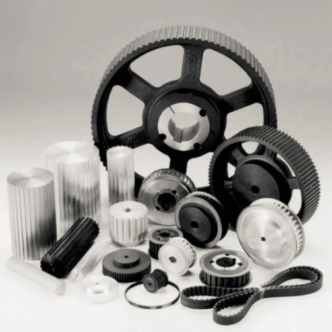 ( in line with variety and width of belts). The material utilised is cast iron EN-GJL-250 UNI EN 1561, and for only some styles it is steel C45 E UNI EN 10083-1. They’ve a smaller prebore that could be machined based on customers?¡¥ prerequisites. Furthermore probably the most prevalent varieties can be found also with taperlock bore.