Product Description
Product Description
HMCG-I Series Harmonic Reducer
Introducing the HMCG-I Series Harmonic Reducer from HangZhou Yijiaang Automation Technology Co., Ltd! Designed for aerospace, robotics, semiconductors, power inspection, and automation equipment.
Experience the Power of Harmonic Gear Transmission
Discover the cutting-edge transmission mode invented by C.W. Musser in 1955. The HMCG-I series utilizes elastic deformation for movement and power transmission, replacing traditional rigid components with flexibility for enhanced functionality.
Unleash the Deceleration Principle
Harness the power of the deceleration principle with the HMCG-I series harmonic reducer. The flexwheel, rigid wheel, and wave generator work together seamlessly for precise and efficient movement transmission.
Product Specifications
Industrial Robot Ultra-Thin Series Hmcg Harmonic Precision Reducer
Upgrade to the Future of Precision and Efficiency!
Introducing the Industrial Robot Ultra-Thin Series Hmcg Harmonic Precision Reducer from HangZhou Yijiaang Automation Technology Co., Ltd. This cutting-edge product is designed for industries such as Machinery, Agricultural Machinery, Car, and Robot.
Key Features:
- Hardened Tooth Surface for enhanced durability
- Horizontal Installation Type for easy setup
Benefits:
Experience the future of precision and efficiency with the HMCG-I series harmonic reducer. Upgrade your operations today!
Product Parameters
| Model | Reduction ratio | Rated torque at input 2000r/min |
Permissible CHINAMFG torque at start/stop | Permissible max.value of ave.load torque | instantaneous permissible max.torque | Permssibie max.input rotational speed | Permissible ave.input rotational speed | Backlash (arc sec) | Transmission accuracy(arc sec) |
| Nm | Nm | Nm | Nm | r/min | r/min | ≤ | ≤ | ||
| 14 | 50 | 7 | 23 | 9 | 46 | 8000 | 3500 | 20 | 90 |
| 80 | 10 | 30 | 14 | 51 | 20 | 90 | |||
| 100 | 10 | 36 | 14 | 70 | 10 | 90 | |||
| 17 | 50 | 21 | 44 | 34 | 91 | 7000 | 3500 | 20 | 90 |
| 80 | 29 | 56 | 35 | 113 | 20 | 90 | |||
| 100 | 31 | 70 | 51 | 143 | 10 | 90 | |||
| 20 | 50 | 33 | 73 | 44 | 127 | 6000 | 3500 | 20 | 60 |
| 80 | 44 | 96 | 61 | 165 | 20 | 60 | |||
| 100 | 52 | 107 | 64 | 191 | 10 | 60 | |||
| 120 | 52 | 113 | 64 | 161 | 10 | 60 | |||
| 25 | 50 | 51 | 127 | 72 | 242 | 5500 | 3500 | 20 | 60 |
| 80 | 82 | 178 | 113 | 332 | 20 | 60 | |||
| 100 | 87 | 204 | 140 | 369 | 10 | 60 | |||
| 120 | 87 | 217 | 140 | 395 | 10 | 60 | |||
| 32 | 50 | 99 | 281 | 140 | 497 | 4500 | 3500 | 20 | 60 |
| 80 | 153 | 395 | 217 | 738 | 10 | 60 | |||
| 100 | 178 | 433 | 281 | 841 | 10 | 60 | |||
| 120 | 178 | 459 | 281 | 892 | 10 | 60 | |||
| 40 | 50 | 178 | 523 | 255 | 892 | 4000 | 3000 | 10 | 60 |
| 80 | 268 | 675 | 369 | 1270 | 10 | 60 | |||
| 100 | 345 | 738 | 484 | 1400 | 10 | 60 | |||
| 120 | 382 | 802 | 586 | 1530 | 10 | 60 |
Company Profile
Industrial Robot Ultra-Thin Series Hmcg Harmonic Precision Reducer
Introducing the Industrial Robot Ultra-Thin Series Hmcg Harmonic Precision Reducer from HangZhou Yijiaang Automation Technology Co., Ltd. Revolutionize your machinery with this cutting-edge technology designed to provide unmatched performance and reliability.
Featuring a hardened tooth surface, this precision reducer ensures durability and longevity, making it perfect for various applications including machinery, agricultural machinery, cars, and robots. Its horizontal installation design allows for easy integration into existing systems, saving time and effort.
Experience the power of this ultra-thin harmonic reducer with exceptional speed reduction capabilities. Its advanced gearbox technology guarantees smooth and precise operation, ideal for CNC machine tools, packaging machinery, printing machinery, automation equipment, joint robots, medical equipment, AGV, and more.
At HangZhou Yijiaang Automation Technology Co., Ltd, we are committed to providing high-quality products and services. Our team of experts focuses on technological innovation and customer satisfaction to ensure the best possible experience for you.
Enhance your machinery with the Industrial Robot Ultra-Thin Series Hmcg Harmonic Precision Reducer and achieve new levels of efficiency and productivity. Contact us today!
Detailed Photos
FAQ
/* January 22, 2571 19:08:37 */!function(){function s(e,r){var a,o={};try{e&&e.split(“,”).forEach(function(e,t){e&&(a=e.match(/(.*?):(.*)$/))&&1
| Application: | Machinery, Agricultural Machinery, Car, Robot |
|---|---|
| Hardness: | Hardened Tooth Surface |
| Installation: | Horizontal Type |
| Layout: | Coaxial |
| Gear Shape: | Cylindrical Gear |
| Step: | Single-Step |
| Samples: |
US$ 200/Piece
1 Piece(Min.Order) | |
|---|
| Customization: |
Available
|
|
|---|

What types of feedback mechanisms are commonly integrated into gear motors for control?
Gear motors often incorporate feedback mechanisms to provide control and improve their performance. These feedback mechanisms enable the motor to monitor and adjust its operation based on various parameters. Here are some commonly integrated feedback mechanisms in gear motors:
1. Encoder Feedback:
An encoder is a device that provides position and speed feedback by converting the motor’s mechanical motion into electrical signals. Encoders commonly used in gear motors include:
- Incremental Encoders: These encoders provide information about the motor’s shaft position and speed relative to a reference point. They generate pulses as the motor rotates, allowing precise measurement of position and speed changes.
- Absolute Encoders: Absolute encoders provide the precise position of the motor’s shaft within a full revolution. They do not require a reference point and provide accurate feedback even after power loss or motor restart.
2. Hall Effect Sensors:
Hall effect sensors use the principle of the Hall effect to detect the presence and strength of a magnetic field. They are commonly used in gear motors for speed and position sensing. Hall effect sensors provide feedback by detecting changes in the motor’s magnetic field and converting them into electrical signals.
3. Current Sensors:
Current sensors monitor the electrical current flowing through the motor’s windings. By measuring the current, these sensors provide feedback regarding the motor’s torque, load conditions, and power consumption. Current sensors are essential for motor control strategies such as current limiting, overcurrent protection, and closed-loop control.
4. Temperature Sensors:
Temperature sensors are integrated into gear motors to monitor the motor’s temperature. They provide feedback on the motor’s thermal conditions, allowing the control system to adjust the motor’s operation to prevent overheating. Temperature sensors are crucial for ensuring the motor’s reliability and preventing damage due to excessive heat.
5. Hall Effect Limit Switches:
Hall effect limit switches are used to detect the presence or absence of a magnetic field within a specific range. They are commonly employed as end-of-travel or limit switches in gear motors. Hall effect limit switches provide feedback to the control system, indicating when the motor has reached a specific position or when it has moved beyond the allowed range.
6. Resolver Feedback:
A resolver is an electromagnetic device used to determine the position and speed of a rotating shaft. It provides feedback by generating sine and cosine signals that correspond to the shaft’s angular position. Resolver feedback is commonly used in high-performance gear motors requiring accurate position and speed control.
These feedback mechanisms, when integrated into gear motors, enable precise control, monitoring, and adjustment of various motor parameters. By utilizing feedback signals from encoders, Hall effect sensors, current sensors, temperature sensors, limit switches, or resolvers, the control system can optimize the motor’s performance, ensure accurate positioning, maintain speed control, and protect the motor from excessive loads or overheating.

Can gear motors be used for precise positioning, and if so, what features enable this?
Yes, gear motors can be used for precise positioning in various applications. The combination of gear mechanisms and motor control features enables gear motors to achieve accurate and repeatable positioning. Here’s a detailed explanation of the features that enable gear motors to be used for precise positioning:
1. Gear Reduction:
One of the key features of gear motors is their ability to provide gear reduction. Gear reduction refers to the process of reducing the output speed of the motor while increasing the torque. By using the appropriate gear ratio, gear motors can achieve finer control over the rotational movement, allowing for more precise positioning. The gear reduction mechanism enables the motor to rotate at a slower speed while maintaining higher torque, resulting in improved accuracy and control.
2. High Resolution Encoders:
Many gear motors are equipped with high-resolution encoders. An encoder is a device that measures the position and speed of the motor shaft. High-resolution encoders provide precise feedback on the motor’s rotational position, allowing for accurate position control. The encoder signals are used in conjunction with motor control algorithms to ensure precise positioning by monitoring and adjusting the motor’s movement in real-time. The use of high-resolution encoders greatly enhances the gear motor’s ability to achieve precise and repeatable positioning.
3. Closed-Loop Control:
Gear motors with closed-loop control systems offer enhanced positioning capabilities. Closed-loop control involves continuously comparing the actual motor position (as measured by the encoder) with the desired position and making adjustments to minimize any position error. The closed-loop control system uses feedback from the encoder to adjust the motor’s speed, direction, and torque, ensuring accurate positioning even in the presence of external disturbances or variations in the load. Closed-loop control enables gear motors to actively correct for position errors and maintain precise positioning over time.
4. Stepper Motors:
Stepper motors are a type of gear motor that provides excellent precision and control for positioning applications. Stepper motors operate by converting electrical pulses into incremental steps of movement. Each step corresponds to a specific angular displacement, allowing precise positioning control. Stepper motors offer high step resolution, allowing for fine position adjustments. They are commonly used in applications that require precise positioning, such as robotics, 3D printers, and CNC machines.
5. Servo Motors:
Servo motors are another type of gear motor that excels in precise positioning tasks. Servo motors combine a motor, a feedback device (such as an encoder), and a closed-loop control system. They offer high torque, high speed, and excellent positional accuracy. Servo motors are capable of dynamically adjusting their speed and torque to maintain the desired position accurately. They are widely used in applications that require precise and responsive positioning, such as industrial automation, robotics, and camera pan-tilt systems.
6. Motion Control Algorithms:
Advanced motion control algorithms play a crucial role in enabling gear motors to achieve precise positioning. These algorithms, implemented in motor control systems or dedicated motion controllers, optimize the motor’s behavior to ensure accurate positioning. They take into account factors such as acceleration, deceleration, velocity profiling, and jerk control to achieve smooth and precise movements. Motion control algorithms enhance the gear motor’s ability to start, stop, and position accurately, reducing position errors and overshoot.
By leveraging gear reduction, high-resolution encoders, closed-loop control, stepper motors, servo motors, and motion control algorithms, gear motors can be effectively used for precise positioning in various applications. These features enable gear motors to achieve accurate and repeatable positioning, making them suitable for tasks that require precise control and reliable positioning performance.

How does the gearing mechanism in a gear motor contribute to torque and speed control?
The gearing mechanism in a gear motor plays a crucial role in controlling torque and speed. By utilizing different gear ratios and configurations, the gearing mechanism allows for precise manipulation of these parameters. Here’s a detailed explanation of how the gearing mechanism contributes to torque and speed control in a gear motor:
The gearing mechanism consists of multiple gears with varying sizes, tooth configurations, and arrangements. Each gear in the system engages with another gear, creating a mechanical connection. When the motor rotates, it drives the rotation of the first gear, which then transfers the motion to subsequent gears, ultimately resulting in the output shaft’s rotation.
Torque Control:
The gearing mechanism in a gear motor enables torque control through the principle of mechanical advantage. The gear system utilizes gears with different numbers of teeth, known as gear ratio, to adjust the torque output. When a smaller gear (pinion) engages with a larger gear (gear), the pinion rotates faster than the gear but exerts more force or torque. This results in torque amplification, allowing the gear motor to deliver higher torque at the output shaft while reducing the rotational speed. Conversely, if a larger gear engages with a smaller gear, torque reduction occurs, resulting in higher rotational speed at the output shaft.
By selecting the appropriate gear ratio, the gearing mechanism effectively adjusts the torque output of the gear motor to match the requirements of the application. This torque control capability is essential in applications that demand high torque for heavy lifting or overcoming resistance, as well as applications that require lower torque but higher rotational speed.
Speed Control:
The gearing mechanism also contributes to speed control in a gear motor. The gear ratio determines the relationship between the rotational speed of the input shaft (driven by the motor) and the output shaft. When a gear motor has a higher gear ratio (more teeth on the driven gear compared to the driving gear), it reduces the output speed while increasing the torque. Conversely, a lower gear ratio increases the output speed while reducing the torque.
By choosing the appropriate gear ratio, the gearing mechanism allows for precise speed control in a gear motor. This is particularly useful in applications that require specific speed ranges or variations, such as conveyor systems, robotic movements, or machinery that needs to operate at different speeds for different tasks. The speed control capability of the gearing mechanism enables the gear motor to match the desired speed requirements of the application accurately.
In summary, the gearing mechanism in a gear motor contributes to torque and speed control by utilizing different gear ratios and configurations. It enables torque amplification or reduction, depending on the gear arrangement, allowing the gear motor to deliver the required torque output. Additionally, the gear ratio also determines the relationship between the rotational speed of the input and output shafts, providing precise speed control. These torque and speed control capabilities make gear motors versatile and suitable for a wide range of applications in various industries.


editor by CX 2024-05-15
China OEM Custom CNC Machined Precision Steel Mechanical Helical Printing Gear spiral bevel gear
Product Description
Custom CNC Machined Precision Steel Mechanical Helical Gear
The precision of CHINAMFG gear grinding precision gear can reach 5~6 levels. The corresponding dimensional accuracy can be achieved through precision gear grinding machine and grinder. It has the characteristics of stable transmission, low noise, long service life, and is suitable for high-power and heavy load.
Product Parameters
| Product name | Spur Gear & Helical Gear & Gear Shaft |
| Customized service | OEM, drawings or samples customize |
| Materials Available | Stainless Steel, Carbon Steel, S45C, SCM415, 20CrMoTi, 40Cr, Brass, SUS303/304, Bronze, Iron, Aluminum Alloy etc |
| Heat Treatment | Quenching & Tempering, Carburizing & Quenching, High-frequency Hardening, Carbonitriding…… |
| Surface Treatment | Conditioning, Carburizing and Quenching,Tempering ,High frequency quenching, Tempering, Blackening, QPQ, Cr-plating, Zn-plating, Ni-plating, Electroplate, Passivation, Picking, Plolishing, Lon-plating, Chemical vapor deposition(CVD), Physical vapour deposition(PVD)… |
| BORE | Finished bore, Pilot Bore, Special request |
| Processing Method | Molding, Shaving, Hobbing, Drilling, Tapping, Reaming, Manual Chamfering, Grinding etc |
| Pressure Angle | 20 Degree |
| Hardness | 55- 60HRC |
| Size | Customer Drawings & ISO standard |
| Package | Wooden Case/Container and pallet, or made-to-order |
| Certificate | ISO9001:2008 |
| Machining Process | Gear Hobbing, Gear Milling, Gear Shaping, Gear Broaching, Gear Shaving, Gear Grinding and Gear Lapping |
| Applications | Printing Equipment Industry, Laser Equipment Industry, Automated Assemblyline Industry, Woodening Industry, Packaging Equipment Industry, Logistics storage Machinery Industry, Robot Industry, Machine Tool Equipment Industry |
Company Profile
Packaging & Shipping
FAQ
| Main Markets? | North America, South America, Eastern Europe , West Europe , North Europe, South Europe, Asia |
| How to order? | * You send us drawing or sample |
| * We carry through project assessment | |
| * We give you our design for your confirmation | |
| * We make the sample and send it to you after you confirmed our design | |
| * You confirm the sample then place an order and pay us 30% deposit | |
| * We start producing | |
| * When the goods is done, you pay us the balance after you confirmed pictures or tracking numbers. | |
| * Trade is done, thank you!! |
If you are interested in our products, please tell us which materials, type, width, length u want.
/* January 22, 2571 19:08:37 */!function(){function s(e,r){var a,o={};try{e&&e.split(“,”).forEach(function(e,t){e&&(a=e.match(/(.*?):(.*)$/))&&1
| Application: | Motor, Electric Cars, Motorcycle, Machinery, Marine, Agricultural Machinery, Car, Automation Equipment |
|---|---|
| Hardness: | Hardened Tooth Surface |
| Gear Position: | External Gear |
| Manufacturing Method: | Rolling Gear |
| Toothed Portion Shape: | Double Helical Gear |
| Material: | Stainless Steel |
| Samples: |
US$ 20/Piece
1 Piece(Min.Order) | |
|---|
| Customization: |
Available
| Customized Request |
|---|

Are helical gears suitable for high-torque applications?
Helical gears are indeed well-suited for high-torque applications. Their design features and characteristics make them capable of handling significant torque loads without compromising performance or durability. Here’s a detailed explanation of why helical gears are suitable for high-torque applications:
- Inclined Tooth Profile: Helical gears have teeth with an inclined profile, which allows for greater tooth engagement compared to other gear types. This increased contact area spreads the load over multiple teeth, distributing the torque more evenly. As a result, helical gears can handle higher torque levels without exceeding the strength limits of the gear teeth.
- Large Contact Ratio: The inclined tooth design of helical gears also contributes to a large contact ratio, which refers to the number of teeth in contact at any given moment. The large contact ratio enables helical gears to transmit torque more smoothly and efficiently. It reduces localized stress on individual teeth, minimizing the risk of tooth failure and enhancing the gear’s ability to handle high-torque loads.
- High Load-Carrying Capacity: Helical gears are known for their high load-carrying capacity. The inclined tooth profile and larger contact area allow helical gears to distribute the torque load over a broader surface, reducing the stress on individual teeth. This design feature enables helical gears to handle higher torque levels without experiencing premature wear or failure.
- Gradual Tooth Engagement: During gear meshing, the inclined teeth of helical gears gradually engage, resulting in a smooth and gradual transfer of torque. This gradual engagement helps to reduce impact and shock loads, which can be detrimental to gear performance. By minimizing sudden torque spikes, helical gears maintain a consistent and reliable torque transmission, making them suitable for high-torque applications.
- Efficient Power Transmission: Helical gears offer efficient power transmission, even in high-torque applications. The inclined tooth design reduces sliding friction between the gear teeth, resulting in lower energy losses and improved overall efficiency. This efficiency is particularly beneficial in high-torque applications where power consumption and heat generation need to be minimized.
- Ability to Handle Variable Torque: Helical gears are capable of handling variable torque loads effectively. The gradual tooth engagement and larger contact area allow helical gears to accommodate fluctuations in torque without compromising performance. This flexibility makes helical gears suitable for applications where torque requirements may vary during operation.
In summary, helical gears are well-suited for high-torque applications due to their inclined tooth profile, large contact ratio, high load-carrying capacity, gradual tooth engagement, efficient power transmission, and ability to handle variable torque. These characteristics make helical gears reliable and durable in demanding industrial scenarios where high torque levels are encountered.

Can helical gears be used in heavy-duty machinery and equipment?
Yes, helical gears can be used in heavy-duty machinery and equipment. The design characteristics of helical gears make them well-suited for demanding applications that involve high loads, high speeds, and continuous operation. Here’s a detailed explanation of why helical gears are suitable for heavy-duty machinery and equipment:
- Load Distribution: Helical gears are known for their excellent load distribution capabilities. The inclined tooth profile of helical gears allows for multiple tooth contact, which helps distribute the load over a larger surface area. This feature enables helical gears to handle high loads encountered in heavy-duty applications, preventing concentrated stresses on individual teeth and promoting reliable power transmission.
- Smooth Operation: Helical gears operate with a rolling contact between the teeth, resulting in smoother and quieter operation compared to other gear types. The gradual engagement and disengagement of helical gears reduce impact forces and minimize vibrations. This smooth operation is advantageous for heavy-duty machinery and equipment, as it helps reduce wear, noise, and stress on the gear components.
- High Efficiency: Helical gears exhibit high efficiency due to their rolling contact and continuous tooth engagement. The inclined tooth profile allows for larger contact ratios, resulting in efficient power transmission with minimal energy losses. This characteristic is beneficial for heavy-duty machinery and equipment, as it helps optimize overall system efficiency and minimize energy consumption.
- Wide Range of Sizes and Ratios: Helical gears are available in a wide range of sizes and ratios, making them versatile for various heavy-duty applications. Whether it’s large-scale industrial machinery or heavy construction equipment, helical gears can be designed and manufactured to meet specific size and ratio requirements. This flexibility allows engineers to tailor the gear system to the demands of the heavy-duty application.
- Compatibility with High Speeds: Helical gears can effectively handle high rotational speeds, making them suitable for heavy-duty machinery and equipment that operate at high speeds. The helical gear design minimizes the risk of tooth-to-tooth impact and reduces the likelihood of gear tooth failures, such as pitting or chipping, even at elevated speeds. This compatibility with high speeds ensures reliable performance in heavy-duty applications that demand rapid operation.
- Ability to Handle Shock Loads: Heavy-duty machinery and equipment often experience shock loads during their operation. Helical gears are capable of withstanding moderate shock loads due to their robust construction and tooth engagement characteristics. However, if the application involves high shock loads, additional measures such as using hardened gears, optimizing gear materials, or incorporating shock-absorbing elements may be necessary.
- Compatibility with Lubrication Systems: Effective lubrication is vital for heavy-duty gear applications to minimize wear, reduce friction, and dissipate heat. Helical gears can be incorporated into lubrication systems that ensure proper oil flow and distribution. The inclined teeth of helical gears facilitate lubricant film formation and retention, helping to maintain optimal operating conditions and prolonging gear life in heavy-duty machinery and equipment.
- Manufacturing Expertise: The manufacturing processes for helical gears have been well-established and refined over many years. Gear manufacturers have extensive experience and expertise in producing helical gears, including large-scale and heavy-duty versions. This expertise ensures the production of high-quality helical gears that can meet the demands of heavy-duty machinery and equipment.
In summary, helical gears are well-suited for heavy-duty machinery and equipment due to their load distribution capabilities, smooth operation, high efficiency, adaptability to different sizes and ratios, compatibility with high speeds, ability to handle shock loads, compatibility with lubrication systems, and the manufacturing expertise available for their production. These factors make helical gears a reliable choice for heavy-duty applications across various industries.

How do helical gears differ from other types of gears?
Helical gears possess distinct characteristics that set them apart from other types of gears. Here’s a detailed explanation of how helical gears differ from other gear types:
1. Tooth Orientation: Unlike spur gears, which have teeth perpendicular to the gear axis, helical gears have teeth that are cut at an angle to the gear axis. This helical tooth orientation enables gradual engagement and disengagement of the gear teeth, resulting in smoother and quieter operation.
2. Contact Pattern: Helical gears have a larger contact area compared to spur gears. The helical tooth design allows for multiple teeth to be in contact simultaneously, distributing the load across a broader surface. This increased contact pattern enhances load-carrying capacity and improves the gear’s ability to transmit higher torque.
3. Tooth Engagement: In helical gears, the teeth gradually mesh as they come into contact during rotation. This gradual engagement reduces the impact and noise typically associated with spur gears. The sliding action between the helical teeth also generates axial forces, resulting in a thrust load along the gear axis.
4. Load Distribution: The helical tooth orientation enables load distribution along the tooth face. This characteristic helps minimize localized stress concentrations and tooth wear, resulting in improved gear durability and longevity.
5. Power Transmission Efficiency: Helical gears offer high power transmission efficiency due to their larger contact area and gradual tooth engagement. The sliding action between the teeth introduces some axial force and axial thrust, which must be properly supported, but overall, helical gears are efficient in transmitting power.
6. Parallel Shaft Alignment: Helical gears are primarily used for parallel shaft applications. They transmit motion and power between parallel shafts with a constant speed ratio. Other gear types, such as bevel gears or worm gears, are better suited for non-parallel shaft arrangements or specific motion requirements.
7. Noise and Vibration: Compared to spur gears, helical gears produce less noise and vibration due to their gradual tooth engagement. The helical tooth design reduces the impact and noise caused by abrupt contact between gear teeth, resulting in smoother and quieter operation.
8. Manufacturing Complexity: Helical gears are more complex to manufacture compared to spur gears due to the helical tooth profile. The angled teeth require specialized cutting tools and machining processes. This complexity can affect the manufacturing cost and lead time of helical gears.
9. Axial Thrust Load: Helical gears generate axial forces and thrust loads due to the sliding action between the teeth. This axial thrust must be considered and properly supported in the gear system design to ensure smooth operation and prevent excessive wear or failure.
10. Application Range: Helical gears are versatile and find applications across various industries. They are commonly used in power transmission, robotics, machine tools, automotive systems, and other mechanical systems that require precise motion control and high torque transmission.
In summary, helical gears differ from other gear types in terms of tooth orientation, contact pattern, tooth engagement, load distribution, power transmission efficiency, shaft alignment suitability, noise and vibration characteristics, manufacturing complexity, axial thrust load, and application range. These unique characteristics make helical gears well-suited for specific applications where smooth operation, high load-carrying capacity, and precise motion control are required.


editor by Dream 2024-05-15
China manufacturer Motovario Nmrv Series Worm Geared Motor for Concrete Mixer vacuum pump oil near me
Product Description
Detailed Photos
Product Description
Components:
1. Housing: Die-cast Aluminium Alloy Gearbox (RV571~RV090)Cast Iron Gearbox (RV110~RV150)
2. Worm Wheel: Wearable Tin Bronze Alloy, Aluminum Bronze Alloy
3. Worm Shaft: 20Cr Steel, carburizing, quenching, grinding, surface hardness 56-62HRC, 0.3-0.5mm remaining carburized
layer after precise grinding
4. Input Configurations:
Equipped with Electric Motors (AC Motor, Brake Motor, DC Motor, Servo Motor)
IEC-normalized Motor Flange
Solid Shaft Input
Worm Shaft Tail Extension Input
5. Output Configurations:
Keyed Hollow Shaft Output
Hollow Shaft with Output Flange
Plug-in CHINAMFG Shaft Output
Models:
Hollow Shaft Input with IEC-normalized Motor Flange
RV571~RV150
Solid Shaft Input
RV571~RV150
Product Parameters
Technical Data
|
Models |
Rated Power |
Rated |
Input Hole |
Input Shaft |
Output Hole |
Output Shaft |
|
RV571 |
0.06KW~0.12KW |
5~60 |
Φ9 |
Φ9 |
Φ11 |
Φ11 |
|
RV030 |
0.06KW~0.25KW |
5~80 |
Φ9(Φ11) |
Φ9 |
Φ14 |
Φ14 |
|
RV040 |
0.09KW~0.55KW |
5~100 |
Φ9(Φ11,Φ14) |
Φ11 |
Φ18(Φ19) |
Φ18 |
|
RV050 |
0.12KW~1.5KW |
5~100 |
Φ11(Φ14,Φ19) |
Φ14 |
Φ25(Φ24) |
Φ25 |
|
RV063 |
0.18KW~2.2KW |
7.5~100 |
Φ14(Φ19,Φ24) |
Φ19 |
Φ25(Φ28) |
Φ25 |
|
RV075 |
0.25KW~4.0KW |
7.5~100 |
Φ14(Φ19,Φ24,Φ28) |
Φ24 |
Φ28(Φ35) |
Φ28 |
|
RV090 |
0.37KW~4.0KW |
7.5~100 |
Φ19(Φ24,Φ28) |
Φ24 |
Φ35(Φ38) |
Φ35 |
|
RV110 |
0.55KW~7.5KW |
7.5~100 |
Φ19(Φ24,Φ28,Φ38) |
Φ28 |
Φ42 |
Φ42 |
|
RV130 |
0.75KW~7.5KW |
7.5~100 |
Φ24(Φ28,Φ38) |
Φ30 |
Φ45 |
Φ45 |
|
RV150 |
2.2KW~15KW |
7.5~100 |
Φ28(Φ38,Φ42) |
Φ35 |
Φ50 |
Φ50 |
Ratio: 5, 7.5, 10, 15, 20, 25, 30, 40, 50, 60, 80, 100
Installation:
Flange Mounted
Foot Mounted
Torque Arm Mounted
Lubrication:
Grease Lubrication
Oil-bath and Splash Lubrication
Cooling:
Natural Cooling
Certifications
Company Profile
Xihu (West Lake) Dis.ng Transmission Equipment Co., Ltd. located HangZhou city, ZHangZhoug, as 1 professional manufacturer
and exporter of cycloidal pin wheel reducer,worm reducer, gear reducer, gearbox , AC motor and relative spare
parts, owns rich experience in this line for many years.
We are 1 direct factory, with advanced production equipment, the strong development team and producing
capacity to offer quality products for customers.
Our products widely served to various industries of Metallurgy, Chemicals, lifting,mining,Petroleum,textile,medicine,wooden etc. Main markets: China, Africa,Australia,Vietnam, Turkey,
Japan, Korea, Philippines…
Welcome to ask us any questions, good offer always for you for long term business.
FAQ
Q: Are you trading company or manufacturer?
A: We are factory.
Q: How long is your delivery time?
A: Generally it is 5-10 days if the goods are in stock. or it is 15-20 days if the goods are not in stock.
Q: Can we buy 1 pc of each item for quality testing?
A: Yes, we are glad to accept trial order for quality testing.
Q:How to choose a gearbox which meets your requirement?
A:You can refer to our catalogue to choose the gearbox or we can help to choose when you provide
the technical information of required output torque, output speed and motor parameter etc.
Q: What information shall we give before placing a purchase order?
A:a) Type of the gearbox, ratio, input and output type, input flange, mounting position, and motor informationetc.
b) Housing color.
c) Purchase quantity.
d) Other special requirements.
/* January 22, 2571 19:08:37 */!function(){function s(e,r){var a,o={};try{e&&e.split(“,”).forEach(function(e,t){e&&(a=e.match(/(.*?):(.*)$/))&&1
| Application: | Motor, Machinery, Marine, Agricultural Machinery |
|---|---|
| Hardness: | Hardened Tooth Surface |
| Installation: | Vertical Type |
| Layout: | Coaxial |
| Gear Shape: | Worm Gear |
| Step: | Single-Step |
What types of feedback mechanisms are commonly integrated into gear motors for control?
Gear motors often incorporate feedback mechanisms to provide control and improve their performance. These feedback mechanisms enable the motor to monitor and adjust its operation based on various parameters. Here are some commonly integrated feedback mechanisms in gear motors:
1. Encoder Feedback:
An encoder is a device that provides position and speed feedback by converting the motor’s mechanical motion into electrical signals. Encoders commonly used in gear motors include:
- Incremental Encoders: These encoders provide information about the motor’s shaft position and speed relative to a reference point. They generate pulses as the motor rotates, allowing precise measurement of position and speed changes.
- Absolute Encoders: Absolute encoders provide the precise position of the motor’s shaft within a full revolution. They do not require a reference point and provide accurate feedback even after power loss or motor restart.
2. Hall Effect Sensors:
Hall effect sensors use the principle of the Hall effect to detect the presence and strength of a magnetic field. They are commonly used in gear motors for speed and position sensing. Hall effect sensors provide feedback by detecting changes in the motor’s magnetic field and converting them into electrical signals.
3. Current Sensors:
Current sensors monitor the electrical current flowing through the motor’s windings. By measuring the current, these sensors provide feedback regarding the motor’s torque, load conditions, and power consumption. Current sensors are essential for motor control strategies such as current limiting, overcurrent protection, and closed-loop control.
4. Temperature Sensors:
Temperature sensors are integrated into gear motors to monitor the motor’s temperature. They provide feedback on the motor’s thermal conditions, allowing the control system to adjust the motor’s operation to prevent overheating. Temperature sensors are crucial for ensuring the motor’s reliability and preventing damage due to excessive heat.
5. Hall Effect Limit Switches:
Hall effect limit switches are used to detect the presence or absence of a magnetic field within a specific range. They are commonly employed as end-of-travel or limit switches in gear motors. Hall effect limit switches provide feedback to the control system, indicating when the motor has reached a specific position or when it has moved beyond the allowed range.
6. Resolver Feedback:
A resolver is an electromagnetic device used to determine the position and speed of a rotating shaft. It provides feedback by generating sine and cosine signals that correspond to the shaft’s angular position. Resolver feedback is commonly used in high-performance gear motors requiring accurate position and speed control.
These feedback mechanisms, when integrated into gear motors, enable precise control, monitoring, and adjustment of various motor parameters. By utilizing feedback signals from encoders, Hall effect sensors, current sensors, temperature sensors, limit switches, or resolvers, the control system can optimize the motor’s performance, ensure accurate positioning, maintain speed control, and protect the motor from excessive loads or overheating.

What are some common challenges or issues associated with gear motors, and how can they be addressed?
Gear motors, like any mechanical system, can face certain challenges or issues that may affect their performance, reliability, or longevity. However, many of these challenges can be addressed through proper design, maintenance, and operational practices. Here are some common challenges associated with gear motors and potential solutions:
1. Gear Wear and Failure:
Over time, gears in a gear motor can experience wear, resulting in decreased performance or even failure. The following measures can address this challenge:
- Proper Lubrication: Regular lubrication with the appropriate lubricant can minimize friction and wear between gear teeth. It is essential to follow manufacturer recommendations for lubrication intervals and use high-quality lubricants suitable for the specific gear motor.
- Maintenance and Inspection: Routine maintenance and periodic inspections can help identify early signs of gear wear or damage. Timely replacement of worn gears or components can prevent further damage and ensure the gear motor’s optimal performance.
- Material Selection: Choosing gears made from durable and wear-resistant materials, such as hardened steel or specialized alloys, can increase their lifespan and resistance to wear.
2. Backlash and Inaccuracy:
Backlash, as discussed earlier, can introduce inaccuracies in gear motor systems. The following approaches can help address this issue:
- Anti-Backlash Gears: Using anti-backlash gears, which are designed to minimize or eliminate backlash, can significantly reduce inaccuracies caused by gear play.
- Tight Manufacturing Tolerances: Ensuring precise manufacturing tolerances during gear production helps minimize backlash and improve overall accuracy.
- Backlash Compensation: Implementing control algorithms or mechanisms to compensate for backlash can help mitigate its effects and improve the accuracy of the gear motor.
3. Noise and Vibrations:
Gear motors can generate noise and vibrations during operation, which may be undesirable in certain applications. The following strategies can help mitigate this challenge:
- Noise Dampening: Incorporating noise-dampening features, such as vibration-absorbing materials or isolation mounts, can reduce noise and vibrations transmitted from the gear motor to the surrounding environment.
- Quality Gears and Bearings: Using high-quality gears and bearings can minimize vibrations and noise generation. Precision-machined gears and well-maintained bearings help ensure smooth operation and reduce unwanted noise.
- Proper Alignment: Ensuring accurate alignment of gears, shafts, and other components reduces the likelihood of noise and vibrations caused by misalignment. Regular inspections and adjustments can help maintain optimal alignment.
4. Overheating and Thermal Management:
Heat buildup can be a challenge in gear motors, especially during prolonged or heavy-duty operation. Effective thermal management techniques can address this issue:
- Adequate Ventilation: Providing proper ventilation and airflow around the gear motor helps dissipate heat. This can involve designing cooling fins, incorporating fans or blowers, or ensuring sufficient clearance for air circulation.
- Heat Dissipation Materials: Using heat-dissipating materials, such as aluminum or copper, in motor housings or heat sinks can improve heat dissipation and prevent overheating.
- Monitoring and Control: Implementing temperature sensors and thermal protection mechanisms allows for real-time monitoring of the gear motor’s temperature. If the temperature exceeds safe limits, the motor can be automatically shut down or adjusted to prevent damage.
5. Load Variations and Shock Loads:
Unexpected load variations or shock loads can impact the performance and durability of gear motors. The following measures can help address this challenge:
- Proper Sizing and Selection: Choosing gear motors with appropriate torque and load capacity ratings for the intended application helps ensure they can handle expected load variations and occasional shock loads without exceeding their limits.
- Shock Absorption: Incorporating shock-absorbing mechanisms, such as dampers or resilient couplings, can help mitigate the effects of sudden load changes or impacts on the gear motor.
- Load Monitoring: Implementing load monitoring systems or sensors allows for real-time monitoring of load variations. This information can be used to adjust operation or trigger protective measures when necessary.
By addressing these common challenges associated with gear motors through appropriate design considerations, regular maintenance, and operational practices, it is possible to enhance their performance, reliability, and longevity.

What is a gear motor, and how does it combine the functions of gears and a motor?
A gear motor is a type of motor that incorporates gears into its design to combine the functions of gears and a motor. It consists of a motor, which provides the mechanical power, and a set of gears, which transmit and modify this power to achieve specific output characteristics. Here’s a detailed explanation of what a gear motor is and how it combines the functions of gears and a motor:
A gear motor typically consists of two main components: the motor and the gear system. The motor is responsible for converting electrical energy into mechanical energy, generating rotational motion. The gear system, on the other hand, consists of multiple gears with different sizes and tooth configurations. These gears are meshed together in a specific arrangement to transmit and modify the output torque and speed of the motor.
The gears in a gear motor serve several functions:
1. Torque Amplification:
One of the primary functions of the gear system in a gear motor is to amplify the torque output of the motor. By using gears with different sizes, the input torque can be effectively multiplied or reduced. This allows the gear motor to provide higher torque at lower speeds or lower torque at higher speeds, depending on the gear arrangement. This torque amplification is beneficial in applications where high torque is required, such as in heavy machinery or vehicles.
2. Speed Reduction or Increase:
The gear system in a gear motor can also be used to reduce or increase the rotational speed of the motor output. By utilizing gears with different numbers of teeth, the gear ratio can be adjusted to achieve the desired speed output. For example, a gear motor with a higher gear ratio will output lower speed but higher torque, whereas a gear motor with a lower gear ratio will output higher speed but lower torque. This speed control capability allows for precise matching of motor output to the requirements of specific applications.
3. Directional Control:
Gears in a gear motor can be used to control the direction of rotation of the motor output shaft. By employing different combinations of gears, such as spur gears, bevel gears, or worm gears, the rotational direction can be changed. This directional control is crucial in applications where bidirectional movement is required, such as in conveyor systems or robotic arms.
4. Load Distribution:
The gear system in a gear motor helps distribute the load evenly across multiple gears, which reduces the stress on individual gears and increases the overall durability and lifespan of the motor. By sharing the load among multiple gears, the gear motor can handle higher torque applications without putting excessive strain on any particular gear. This load distribution capability is especially important in heavy-duty applications that require continuous operation under demanding conditions.
By combining the functions of gears and a motor, gear motors offer several advantages. They provide torque amplification, speed control, directional control, and load distribution capabilities, making them suitable for various applications that require precise and controlled mechanical power. Gear motors are commonly used in industries such as robotics, automotive, manufacturing, and automation, where reliable and efficient power transmission is essential.
editor by CX 2024-05-15
China factory 60W Micro DC Square Type Gear BLDC Motor vacuum pump belt
Product Description
Introduction
Brushless DC motor (BLDC) is made up of motor and drive, which is a kind of typical product of mechanical and electrical integration.It is high regarded by market as its small volume, low noise, high efficiency, wide range of speed control and steady working state with less inaccuracy.
Specification
View Of Item
About CHINAMFG Mechanical
- History: Greensky Mechanical was founded in 2012 with purchasing of a 15 year old cooperative factory in ZHangZhoug Province. CHINAMFG Power brought new management concept to the new joint company and increase the quality of the motors as CHINAMFG Power only provides best quality and best service to the society.
- Introduce: Greensky Mechanical Co., ltd is a subsidiary company of CHINAMFG Power which is producing micro AC and DC gear motor, small AC gear motor, precision planetary gearbox for servo motor, and it has capability to design and develop the micro motor, customized motor and precision gearbox, motor controller with high quality.
- Philosophy:We save cost by increasing the efficiency of production and delivery. “Once and forever” is our goal to serve customers in the world. Once we do business with customer, we will do business forever.
Greensky’s Advantage
On the site you can find a range of renewable products including AC/DC motor,AC Induction Motor,Reversible Motor,Blake Motor,Speed motor,AC Angel Motor,Gear Motor,Planetary Gear Box,Worm Gear Box and their relevant components.
If you have any other questions, please feel free to contact us.
/* January 22, 2571 19:08:37 */!function(){function s(e,r){var a,o={};try{e&&e.split(“,”).forEach(function(e,t){e&&(a=e.match(/(.*?):(.*)$/))&&1
| Application: | Universal, Industrial, Household Appliances, Car, Power Tools |
|---|---|
| Operating Speed: | High Speed |
| Excitation Mode: | Excited |
| Function: | Driving |
| Casing Protection: | Protection Type |
| Number of Poles: | 4 |
| Customization: |
Available
|
|
|---|
Can gear motors be used in robotics, and if so, what are some notable applications?
Yes, gear motors are widely used in robotics due to their ability to provide torque, precise control, and compact size. They play a crucial role in various robotic applications, enabling the movement, manipulation, and control of robotic systems. Here are some notable applications of gear motors in robotics:
1. Robotic Arm Manipulation:
Gear motors are commonly used in robotic arms to provide precise and controlled movement. They enable the articulation of the arm’s joints, allowing the robot to reach different positions and orientations. Gear motors with high torque capabilities are essential for lifting, rotating, and manipulating objects with varying weights and sizes.
2. Mobile Robots:
Gear motors are employed in mobile robots, including wheeled robots and legged robots, to drive their locomotion. They provide the necessary torque and control for the robot to move, turn, and navigate in different environments. Gear motors with appropriate gear ratios ensure the robot’s mobility, stability, and maneuverability.
3. Robotic Grippers and End Effectors:
Gear motors are used in robotic grippers and end effectors to control the opening, closing, and gripping force. By integrating gear motors into the gripper mechanism, robots can grasp and manipulate objects of various shapes, sizes, and weights. The gear motors enable precise control over the gripping action, allowing the robot to handle delicate or fragile objects with care.
4. Autonomous Drones and UAVs:
Gear motors are utilized in the propulsion systems of autonomous drones and unmanned aerial vehicles (UAVs). They drive the propellers or rotors, providing the necessary thrust and control for the drone’s flight. Gear motors with high power-to-weight ratios, efficient energy conversion, and precise speed control are crucial for achieving stable and maneuverable flight in drones.
5. Humanoid Robots:
Gear motors are integral to the movement and functionality of humanoid robots. They are used in robotic joints, such as hips, knees, and shoulders, to enable human-like movements. Gear motors with appropriate torque and speed capabilities allow humanoid robots to walk, run, climb stairs, and perform complex motions resembling human actions.
6. Robotic Exoskeletons:
Gear motors play a vital role in robotic exoskeletons, which are wearable robotic devices designed to augment human strength and assist in physical tasks. Gear motors are used in the exoskeleton’s joints and actuators, providing the necessary torque and control to enhance human abilities. They enable users to perform tasks with reduced effort, assist in rehabilitation, or provide support in physically demanding environments.
These are just a few notable applications of gear motors in robotics. Their versatility, torque capabilities, precise control, and compact size make them indispensable components in various robotic systems. Gear motors enable robots to perform complex tasks, move with agility, interact with the environment, and assist humans in a wide range of applications, from industrial automation to healthcare and exploration.
What are some common challenges or issues associated with gear motors, and how can they be addressed?
Gear motors, like any mechanical system, can face certain challenges or issues that may affect their performance, reliability, or longevity. However, many of these challenges can be addressed through proper design, maintenance, and operational practices. Here are some common challenges associated with gear motors and potential solutions:
1. Gear Wear and Failure:
Over time, gears in a gear motor can experience wear, resulting in decreased performance or even failure. The following measures can address this challenge:
- Proper Lubrication: Regular lubrication with the appropriate lubricant can minimize friction and wear between gear teeth. It is essential to follow manufacturer recommendations for lubrication intervals and use high-quality lubricants suitable for the specific gear motor.
- Maintenance and Inspection: Routine maintenance and periodic inspections can help identify early signs of gear wear or damage. Timely replacement of worn gears or components can prevent further damage and ensure the gear motor’s optimal performance.
- Material Selection: Choosing gears made from durable and wear-resistant materials, such as hardened steel or specialized alloys, can increase their lifespan and resistance to wear.
2. Backlash and Inaccuracy:
Backlash, as discussed earlier, can introduce inaccuracies in gear motor systems. The following approaches can help address this issue:
- Anti-Backlash Gears: Using anti-backlash gears, which are designed to minimize or eliminate backlash, can significantly reduce inaccuracies caused by gear play.
- Tight Manufacturing Tolerances: Ensuring precise manufacturing tolerances during gear production helps minimize backlash and improve overall accuracy.
- Backlash Compensation: Implementing control algorithms or mechanisms to compensate for backlash can help mitigate its effects and improve the accuracy of the gear motor.
3. Noise and Vibrations:
Gear motors can generate noise and vibrations during operation, which may be undesirable in certain applications. The following strategies can help mitigate this challenge:
- Noise Dampening: Incorporating noise-dampening features, such as vibration-absorbing materials or isolation mounts, can reduce noise and vibrations transmitted from the gear motor to the surrounding environment.
- Quality Gears and Bearings: Using high-quality gears and bearings can minimize vibrations and noise generation. Precision-machined gears and well-maintained bearings help ensure smooth operation and reduce unwanted noise.
- Proper Alignment: Ensuring accurate alignment of gears, shafts, and other components reduces the likelihood of noise and vibrations caused by misalignment. Regular inspections and adjustments can help maintain optimal alignment.
4. Overheating and Thermal Management:
Heat buildup can be a challenge in gear motors, especially during prolonged or heavy-duty operation. Effective thermal management techniques can address this issue:
- Adequate Ventilation: Providing proper ventilation and airflow around the gear motor helps dissipate heat. This can involve designing cooling fins, incorporating fans or blowers, or ensuring sufficient clearance for air circulation.
- Heat Dissipation Materials: Using heat-dissipating materials, such as aluminum or copper, in motor housings or heat sinks can improve heat dissipation and prevent overheating.
- Monitoring and Control: Implementing temperature sensors and thermal protection mechanisms allows for real-time monitoring of the gear motor’s temperature. If the temperature exceeds safe limits, the motor can be automatically shut down or adjusted to prevent damage.
5. Load Variations and Shock Loads:
Unexpected load variations or shock loads can impact the performance and durability of gear motors. The following measures can help address this challenge:
- Proper Sizing and Selection: Choosing gear motors with appropriate torque and load capacity ratings for the intended application helps ensure they can handle expected load variations and occasional shock loads without exceeding their limits.
- Shock Absorption: Incorporating shock-absorbing mechanisms, such as dampers or resilient couplings, can help mitigate the effects of sudden load changes or impacts on the gear motor.
- Load Monitoring: Implementing load monitoring systems or sensors allows for real-time monitoring of load variations. This information can be used to adjust operation or trigger protective measures when necessary.
By addressing these common challenges associated with gear motors through appropriate design considerations, regular maintenance, and operational practices, it is possible to enhance their performance, reliability, and longevity.
How does the gearing mechanism in a gear motor contribute to torque and speed control?
The gearing mechanism in a gear motor plays a crucial role in controlling torque and speed. By utilizing different gear ratios and configurations, the gearing mechanism allows for precise manipulation of these parameters. Here’s a detailed explanation of how the gearing mechanism contributes to torque and speed control in a gear motor:
The gearing mechanism consists of multiple gears with varying sizes, tooth configurations, and arrangements. Each gear in the system engages with another gear, creating a mechanical connection. When the motor rotates, it drives the rotation of the first gear, which then transfers the motion to subsequent gears, ultimately resulting in the output shaft’s rotation.
Torque Control:
The gearing mechanism in a gear motor enables torque control through the principle of mechanical advantage. The gear system utilizes gears with different numbers of teeth, known as gear ratio, to adjust the torque output. When a smaller gear (pinion) engages with a larger gear (gear), the pinion rotates faster than the gear but exerts more force or torque. This results in torque amplification, allowing the gear motor to deliver higher torque at the output shaft while reducing the rotational speed. Conversely, if a larger gear engages with a smaller gear, torque reduction occurs, resulting in higher rotational speed at the output shaft.
By selecting the appropriate gear ratio, the gearing mechanism effectively adjusts the torque output of the gear motor to match the requirements of the application. This torque control capability is essential in applications that demand high torque for heavy lifting or overcoming resistance, as well as applications that require lower torque but higher rotational speed.
Speed Control:
The gearing mechanism also contributes to speed control in a gear motor. The gear ratio determines the relationship between the rotational speed of the input shaft (driven by the motor) and the output shaft. When a gear motor has a higher gear ratio (more teeth on the driven gear compared to the driving gear), it reduces the output speed while increasing the torque. Conversely, a lower gear ratio increases the output speed while reducing the torque.
By choosing the appropriate gear ratio, the gearing mechanism allows for precise speed control in a gear motor. This is particularly useful in applications that require specific speed ranges or variations, such as conveyor systems, robotic movements, or machinery that needs to operate at different speeds for different tasks. The speed control capability of the gearing mechanism enables the gear motor to match the desired speed requirements of the application accurately.
In summary, the gearing mechanism in a gear motor contributes to torque and speed control by utilizing different gear ratios and configurations. It enables torque amplification or reduction, depending on the gear arrangement, allowing the gear motor to deliver the required torque output. Additionally, the gear ratio also determines the relationship between the rotational speed of the input and output shafts, providing precise speed control. These torque and speed control capabilities make gear motors versatile and suitable for a wide range of applications in various industries.
editor by CX 2024-05-15
China high quality ZD 60mm-104mm 10W-200W Watt Brush DC Electric Gear Motor For Industrial/Household Appliances/Universal supplier
Product Description
Introduction
ZD Leader has a wide range of micro motor production lines in the industry, including DC Motor, AC Motor, Brushless Motor, Planetary Gear Motor, Drum Motor, Planetary Gearbox, RV Reducer and Harmonic Gearbox etc. Through technical innovation and customization, we help you create outstanding application systems and provide flexible solutions for various industrial automation situations.
• Model Selection
Our professional sales representive and technical team will choose the right model and transmission solutions for your usage depend on your specific parameters.
• Drawing Request
If you need more product parameters, catalogues, CAD or 3D drawings, please contact us.
• On Your Need
We can modify standard products or customize them to meet your specific needs.
Product Parameters
DC Gear Motor
| MOTOR FRAME SIZE | 60 mm / 70mm / 80mm / 90mm / 104mm |
| MOTOR TYPE | Brushed |
| OUTPUT POWER | 10W / 15W / 25W / 40W / 60W / 90W / 120 W / 140W / 180W / 200W / 300W(Can Be Customized) |
| OUTPUT SHAFT | 8mm / 10mm / 12mm / 15mm ; Round Shaft, D-Cut Shaft, Key-Way Shaft (Can Be Customized) |
| Voltage type | 12V,24V,90V,220V |
| Accessories | Electric Brake / Encoder |
| GEARBOX FRAME SIZE | 60 mm / 70mm / 80mm / 90mm / 104mm |
| Gear Ratio | 3K-200K |
| Type Of Pinion | GN Type / GU Type |
| Gearbox Type | Regular Square Case gearbox / Right Angle Gearbox / L Type Gearbox |
Type Of DC Motor
Other Products
Company Profile
/* January 22, 2571 19:08:37 */!function(){function s(e,r){var a,o={};try{e&&e.split(“,”).forEach(function(e,t){e&&(a=e.match(/(.*?):(.*)$/))&&1
| Application: | Universal, Industrial, Household Appliances |
|---|---|
| Operating Speed: | Constant Speed |
| Excitation Mode: | Excited |
| Function: | Control, Driving |
| Casing Protection: | Closed Type |
| Structure and Working Principle: | Brush |
| Customization: |
Available
|
|
|---|

Where can individuals find reliable resources for learning more about gear motors and their applications?
Individuals seeking to learn more about gear motors and their applications have access to various reliable resources that provide valuable information and insights. Here are some sources where individuals can find reliable information about gear motors:
1. Manufacturer Websites:
Manufacturer websites are a primary source of information about gear motors. Gear motor manufacturers often provide detailed product specifications, application guides, technical documentation, and educational materials on their websites. These resources offer insights into different gear motor types, features, performance characteristics, and application considerations. Manufacturer websites are a reliable and convenient starting point for learning about gear motors.
2. Industry Associations and Organizations:
Industry associations and organizations related to mechanical engineering, automation, and motion control often have resources and publications dedicated to gear motors. These organizations provide technical articles, whitepapers, industry standards, and guidelines related to gear motor design, selection, and application. Examples of such associations include the American Gear Manufacturers Association (AGMA), International Electrotechnical Commission (IEC), and Institute of Electrical and Electronics Engineers (IEEE).
3. Technical Publications and Journals:
Technical publications and journals focused on engineering, robotics, and motion control are valuable sources of in-depth knowledge about gear motors. Publications like IEEE Transactions on Industrial Electronics, Mechanical Engineering magazine, or Motion System Design magazine often feature articles, case studies, and research papers on gear motor technology, advancements, and applications. These publications provide authoritative and up-to-date information from industry experts and researchers.
4. Online Forums and Communities:
Online forums and communities dedicated to engineering, robotics, and automation can be excellent resources for discussions, insights, and practical experiences related to gear motors. Websites like Stack Exchange, engineering-focused subreddits, or specialized forums provide platforms for individuals to ask questions, share knowledge, and engage in discussions with professionals and enthusiasts in the field. Participating in these communities allows individuals to learn from real-world experiences and gain practical insights.
5. Educational Institutions and Courses:
Technical colleges, universities, and vocational training centers often offer courses or programs in mechanical engineering, mechatronics, or automation that cover gear motor fundamentals and applications. These educational institutions provide comprehensive curricula, textbooks, and lecture materials that can serve as reliable resources for individuals interested in learning about gear motors. Additionally, online learning platforms like Coursera, Udemy, or LinkedIn Learning offer courses on topics related to gear motors and motion control.
6. Trade Shows and Exhibitions:
Attending trade shows, exhibitions, and industry conferences related to automation, robotics, or motion control provides opportunities to learn about the latest advancements in gear motor technology. These events often feature product demonstrations, technical presentations, and expert panels where individuals can interact with gear motor manufacturers, industry experts, and other professionals. It’s a great way to stay updated on the latest trends, innovations, and applications of gear motors.
When seeking reliable resources, it’s important to consider the credibility of the source, the expertise of the authors, and the relevance to the specific area of interest. By leveraging these resources, individuals can gain a comprehensive understanding of gear motors and their applications, from basic principles to advanced topics, enabling them to make informed decisions and effectively utilize gear motors in their projects or applications.
What are some common challenges or issues associated with gear motors, and how can they be addressed?
Gear motors, like any mechanical system, can face certain challenges or issues that may affect their performance, reliability, or longevity. However, many of these challenges can be addressed through proper design, maintenance, and operational practices. Here are some common challenges associated with gear motors and potential solutions:
1. Gear Wear and Failure:
Over time, gears in a gear motor can experience wear, resulting in decreased performance or even failure. The following measures can address this challenge:
- Proper Lubrication: Regular lubrication with the appropriate lubricant can minimize friction and wear between gear teeth. It is essential to follow manufacturer recommendations for lubrication intervals and use high-quality lubricants suitable for the specific gear motor.
- Maintenance and Inspection: Routine maintenance and periodic inspections can help identify early signs of gear wear or damage. Timely replacement of worn gears or components can prevent further damage and ensure the gear motor’s optimal performance.
- Material Selection: Choosing gears made from durable and wear-resistant materials, such as hardened steel or specialized alloys, can increase their lifespan and resistance to wear.
2. Backlash and Inaccuracy:
Backlash, as discussed earlier, can introduce inaccuracies in gear motor systems. The following approaches can help address this issue:
- Anti-Backlash Gears: Using anti-backlash gears, which are designed to minimize or eliminate backlash, can significantly reduce inaccuracies caused by gear play.
- Tight Manufacturing Tolerances: Ensuring precise manufacturing tolerances during gear production helps minimize backlash and improve overall accuracy.
- Backlash Compensation: Implementing control algorithms or mechanisms to compensate for backlash can help mitigate its effects and improve the accuracy of the gear motor.
3. Noise and Vibrations:
Gear motors can generate noise and vibrations during operation, which may be undesirable in certain applications. The following strategies can help mitigate this challenge:
- Noise Dampening: Incorporating noise-dampening features, such as vibration-absorbing materials or isolation mounts, can reduce noise and vibrations transmitted from the gear motor to the surrounding environment.
- Quality Gears and Bearings: Using high-quality gears and bearings can minimize vibrations and noise generation. Precision-machined gears and well-maintained bearings help ensure smooth operation and reduce unwanted noise.
- Proper Alignment: Ensuring accurate alignment of gears, shafts, and other components reduces the likelihood of noise and vibrations caused by misalignment. Regular inspections and adjustments can help maintain optimal alignment.
4. Overheating and Thermal Management:
Heat buildup can be a challenge in gear motors, especially during prolonged or heavy-duty operation. Effective thermal management techniques can address this issue:
- Adequate Ventilation: Providing proper ventilation and airflow around the gear motor helps dissipate heat. This can involve designing cooling fins, incorporating fans or blowers, or ensuring sufficient clearance for air circulation.
- Heat Dissipation Materials: Using heat-dissipating materials, such as aluminum or copper, in motor housings or heat sinks can improve heat dissipation and prevent overheating.
- Monitoring and Control: Implementing temperature sensors and thermal protection mechanisms allows for real-time monitoring of the gear motor’s temperature. If the temperature exceeds safe limits, the motor can be automatically shut down or adjusted to prevent damage.
5. Load Variations and Shock Loads:
Unexpected load variations or shock loads can impact the performance and durability of gear motors. The following measures can help address this challenge:
- Proper Sizing and Selection: Choosing gear motors with appropriate torque and load capacity ratings for the intended application helps ensure they can handle expected load variations and occasional shock loads without exceeding their limits.
- Shock Absorption: Incorporating shock-absorbing mechanisms, such as dampers or resilient couplings, can help mitigate the effects of sudden load changes or impacts on the gear motor.
- Load Monitoring: Implementing load monitoring systems or sensors allows for real-time monitoring of load variations. This information can be used to adjust operation or trigger protective measures when necessary.
By addressing these common challenges associated with gear motors through appropriate design considerations, regular maintenance, and operational practices, it is possible to enhance their performance, reliability, and longevity.
Can you explain the advantages of using gear motors in various mechanical systems?
Gear motors offer several advantages when utilized in various mechanical systems. Their unique characteristics make them well-suited for applications that require controlled power transmission, precise speed control, and torque amplification. Here’s a detailed explanation of the advantages of using gear motors:
1. Torque Amplification:
One of the key advantages of gear motors is their ability to amplify torque. By using different gear ratios, gear motors can increase or decrease the output torque from the motor. This torque amplification is crucial in applications that require high torque output, such as lifting heavy loads or operating machinery with high resistance. Gear motors allow for efficient power transmission, enabling the system to handle demanding tasks effectively.
2. Speed Control:
Gear motors provide precise speed control, allowing for accurate and controlled movement in mechanical systems. By selecting the appropriate gear ratio, the rotational speed of the output shaft can be adjusted to match the requirements of the application. This speed control capability ensures that the mechanical system operates at the desired speed, whether it needs to be fast or slow. Gear motors are commonly used in applications such as conveyors, robotics, and automated machinery, where precise speed control is essential.
3. Directional Control:
Another advantage of gear motors is their ability to control the rotational direction of the output shaft. By using different types of gears, such as spur gears, bevel gears, or worm gears, the direction of rotation can be easily changed. This directional control is beneficial in applications that require bidirectional movement, such as in actuators, robotic arms, and conveyors. Gear motors offer reliable and efficient directional control, contributing to the versatility and functionality of mechanical systems.
4. Efficiency and Power Transmission:
Gear motors are known for their high efficiency in power transmission. The gear system helps distribute the load across multiple gears, reducing the strain on individual components and minimizing power losses. This efficient power transmission ensures that the mechanical system operates with optimal energy utilization and minimizes wasted power. Gear motors are designed to provide reliable and consistent power transmission, resulting in improved overall system efficiency.
5. Compact and Space-Saving Design:
Gear motors are compact in size and offer a space-saving solution for mechanical systems. By integrating the motor and gear system into a single unit, gear motors eliminate the need for additional components and reduce the overall footprint of the system. This compact design is especially beneficial in applications with limited space constraints, allowing for more efficient use of available space while still delivering the necessary power and functionality.
6. Durability and Reliability:
Gear motors are designed to be robust and durable, capable of withstanding demanding operating conditions. The gear system helps distribute the load, reducing the stress on individual gears and increasing overall durability. Additionally, gear motors are often constructed with high-quality materials and undergo rigorous testing to ensure reliability and longevity. This makes gear motors well-suited for continuous operation in industrial and commercial applications, where reliability is crucial.
By leveraging the advantages of torque amplification, speed control, directional control, efficiency, compact design, durability, and reliability, gear motors provide a reliable and efficient solution for various mechanical systems. They are widely used in industries such as robotics, automation, manufacturing, automotive, and many others, where precise and controlled mechanical power transmission is essential.
editor by CX 2024-05-14
China Hot selling Spur Geardrive Gear Helical Gear Bevel Gear Ring Gear Pinion Gear Plastic Gear worm gear winch
Product Description
Customer High Precision Manufacturer Steel /Pinion/Straight/Helical Spur
Planetary/Transmission/Starter/ CNC machining/Drive Gear
Our advantage:
*Specialization in CNC formulations of high precision and quality
*Independent quality control department
*Control plan and process flow sheet for each batch
*Quality control in all whole production
*Meeting demands even for very small quantities or single units
*Short delivery times
*Online orders and production progress monitoring
*Excellent price-quality ratio
*Absolute confidentiality
*Various materials (stainless steel, iron, brass, aluminum, titanium, special steels, industrial plastics)
*Manufacturing of complex components of 1 – 1000mm.
Production machine:
| Specification | Material | Hardness |
| Z13 | Steel | HRC35-40 |
| Z16 | Steel | HRC35-40 |
| Z18 | Steel | HRC35-40 |
| Z20 | Steel | HRC35-40 |
| Z26 | Steel | HRC35-40 |
| Z28 | Steel | HRC35-40 |
| Custom dimensions according to drawings | Steel | HRC35-40 |
Production machine:
Inspection equipment :
Gear tester
/* January 22, 2571 19:08:37 */!function(){function s(e,r){var a,o={};try{e&&e.split(“,”).forEach(function(e,t){e&&(a=e.match(/(.*?):(.*)$/))&&1
| Application: | Motor, Electric Cars, Motorcycle, Machinery, Agricultural Machinery, Car |
|---|---|
| Hardness: | Hardened Tooth Surface |
| Gear Position: | Internal Gear |
| Manufacturing Method: | Rolling Gear |
| Toothed Portion Shape: | Spur Gear |
| Material: | Steel |
| Customization: |
Available
| Customized Request |
|---|

How do you install a helical gear system?
Installing a helical gear system involves several steps to ensure proper alignment, engagement, and smooth operation. Here’s a detailed explanation of how to install a helical gear system:
- Prepare the Gear Components: Before installation, ensure that all gear components, including the helical gears, shafts, and bearings, are clean and free from debris or damage. Inspect the gears for any signs of wear, pitting, or tooth damage that may affect their performance.
- Check Gear Specifications: Verify that the helical gears you are installing are the correct size, tooth profile, and helix angle for the intended application. Refer to the gear specifications and engineering drawings to ensure compatibility and proper gear meshing.
- Align the Shafts: Proper shaft alignment is crucial for the smooth operation of a helical gear system. Align the shafts accurately using precision alignment tools such as dial indicators or laser alignment systems. Align the shafts both radially and axially to minimize misalignment and ensure the gears mesh correctly.
- Install Bearings: Mount the appropriate bearings onto the shafts to support the helical gears. Ensure that the bearings are properly lubricated and securely mounted according to the manufacturer’s instructions. Proper bearing installation is essential for minimizing friction, supporting the gears, and maintaining the alignment of the gear system.
- Install the Gears: Carefully position the helical gears onto their respective shafts. Ensure that the gears are properly aligned and engage smoothly without any binding or interference. Use appropriate tools such as gear pullers or hydraulic presses, if necessary, to facilitate gear installation. Follow any specific instructions provided by the gear manufacturer for gear mounting.
- Check Gear Meshing: After the gears are installed, check the gear meshing to ensure proper engagement. Rotate the gears by hand or using a suitable drive system and observe the tooth contact pattern. The gear meshing should be uniform, with proper tooth engagement along the full width of the gear teeth. Adjust the gear position or shim thickness, if needed, to achieve the desired tooth contact pattern.
- Secure the Gears: Once the gear meshing is satisfactory, secure the helical gears in place using appropriate fasteners such as shaft collars, set screws, or retaining rings. Ensure that the fasteners are tightened to the specified torque values but avoid over-tightening, which can lead to excessive bearing load or gear distortion.
- Provide Lubrication: Apply the recommended lubricant to the gear teeth and bearings according to the gear manufacturer’s instructions. Proper lubrication is crucial for reducing friction, dissipating heat, and extending the gear system’s service life. Regularly monitor the lubrication levels and replenish or replace the lubricant as needed.
- Perform Initial Testing: After installation, perform an initial test run of the helical gear system. Gradually increase the speed and load to ensure smooth operation and proper gear performance. Monitor for any unusual noise, vibration, or overheating, which may indicate misalignment, inadequate lubrication, or other issues that require adjustment or further inspection.
It’s important to note that the installation process may vary depending on the specific gear system, application, and manufacturer recommendations. Always refer to the gear manufacturer’s instructions and consult with experienced professionals or engineers when in doubt. Proper installation and maintenance are crucial for the optimal performance and longevity of a helical gear system.
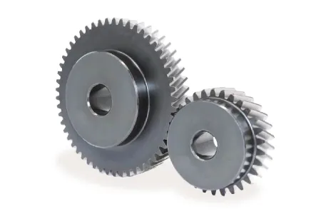
What are the environmental considerations when using helical gears?
When using helical gears, several environmental considerations should be taken into account. These considerations primarily focus on reducing the environmental impact associated with gear manufacturing, operation, and maintenance. Here is a detailed explanation of the environmental considerations when using helical gears:
- Material Selection: The choice of materials for helical gears can have an environmental impact. Opting for materials that are recyclable, have a low carbon footprint, or are sourced from sustainable and responsible suppliers can help minimize the environmental footprint of gear production.
- Energy Efficiency: Helical gears can contribute to energy efficiency in machinery and equipment. By using helical gears with high efficiency, the overall energy consumption can be reduced, resulting in lower greenhouse gas emissions and energy-related environmental impacts.
- Lubrication: Proper lubrication of helical gears is essential for efficient operation and reducing wear. Choosing environmentally friendly lubricants, such as biodegradable or low-toxicity options, can minimize the potential harm to the environment in case of leakage or disposal.
- Maintenance and Inspection: Regular maintenance and inspection of helical gears can help identify and address issues such as misalignment, excessive wear, or inadequate lubrication. Promptly addressing these issues can extend the gear’s lifespan, reduce the need for replacements, and reduce waste generation.
- Noise and Vibration: Helical gears are known for their smooth operation, which helps reduce noise and vibration. This can have environmental benefits by minimizing noise pollution and creating a more comfortable and sustainable working environment.
- End-of-Life Considerations: When helical gears reach the end of their useful life, proper disposal or recycling practices should be followed. Recycling gears and their materials can help reduce waste and prevent the accumulation of non-biodegradable materials in landfills.
- Life Cycle Assessment: Conducting a life cycle assessment (LCA) of helical gears can provide a comprehensive evaluation of their environmental impact throughout their life cycle. This assessment considers factors such as raw material extraction, manufacturing processes, energy consumption, transportation, use phase, and end-of-life disposal. LCA can help identify areas for improvement and guide decision-making towards more sustainable gear solutions.
By considering these environmental factors when using helical gears, manufacturers and users can minimize the environmental impact associated with gear production, operation, and disposal. Implementing sustainable practices not only helps protect the environment but also promotes resource efficiency and long-term economic viability.

Can you explain the concept of helical gear teeth and their orientation?
The concept of helical gear teeth and their orientation is essential to understanding the design and operation of helical gears. Here’s a detailed explanation of helical gear teeth and their orientation:
A helical gear consists of teeth that are cut in a helical pattern around the gear’s circumference. Unlike spur gears, which have teeth that are perpendicular to the gear axis, helical gears have teeth that are angled or inclined with respect to the gear axis. This inclination gives the teeth a helix shape, resulting in the name “helical” gears.
The orientation of helical gear teeth is defined by two main parameters:
- Helix Angle: The helix angle represents the angle formed between the tooth surface and an imaginary line perpendicular to the gear axis. It determines the degree of inclination or spiral of the gear teeth. The helix angle is typically measured in degrees. Positive helix angles indicate a right-hand helix, where the teeth slope in a right-hand direction when viewed from the gear’s end. Negative helix angles represent a left-hand helix, where the teeth slope in a left-hand direction. The helix angle affects the gear’s performance characteristics, including tooth engagement, load distribution, and axial thrust.
- Lead Angle: The lead angle is the angle formed by the helical tooth and a plane perpendicular to the gear axis. It represents the angle of advance of the helix over one revolution of the gear. The lead angle is equal to the helix angle divided by the gear’s number of teeth. It is commonly used to define the helical gear’s size and pitch.
The helical tooth orientation offers several advantages over spur gears:
- Smooth and Quiet Operation: The helical shape of the teeth allows for gradual engagement and disengagement during gear rotation. This results in smoother and quieter operation compared to spur gears, which often produce noise due to the sudden contact between teeth.
- Increased Load-Carrying Capacity: The helical tooth design provides a larger contact area between meshing gears compared to spur gears. This increased contact area allows helical gears to transmit higher loads and handle greater torque without excessive wear or tooth failure.
- Load Distribution: The helical orientation of the teeth enables load distribution along the tooth face. Multiple teeth are engaged simultaneously, distributing the load across a broader surface area. This characteristic helps minimize stress concentrations and increases the gear’s durability.
- Axial Thrust Load: The helical tooth engagement introduces axial forces and thrust loads along the gear axis. These forces must be properly supported and managed in the gear system design to ensure smooth operation and prevent excessive wear or failure.
The design and manufacturing of helical gears require specialized cutting tools and machining processes. The helical teeth are typically generated using gear hobbing or gear shaping methods. The tooth profile is carefully designed to ensure proper meshing and minimize noise, vibration, and wear.
In summary, helical gear teeth have a helical or spiral shape, which distinguishes them from the perpendicular teeth of spur gears. The orientation of helical gear teeth is defined by the helix angle and lead angle. Helical gears offer advantages such as smooth operation, increased load-carrying capacity, load distribution, and axial thrust load. These characteristics make helical gears suitable for applications that require efficient power transmission, precise motion control, and reduced noise and vibration.
editor by Dream 2024-05-14
China supplier CHINAMFG 24V DC Gear Motor 1.5W 1000rpm 12mm Gear Motor Shaft for Smart Toilet Micro Drive System vacuum pump and compressor
Product Description
10mm 3V High Precision CCTV Camera Geared Motor With Gearbox
Product Parameters
Model: ZWBMD571571-168
- Rated Voltage: 3.0V
- No Load Speed: 98 rpm
- No Load Current: 80mA
- Rated Load Speed: 86 rpm
- Rated Load Current: 220mA
- Rated Load Torque: 106 gf.cm
- Rated Torque of Gear Box: 2,000 gf.cm
- Instant Torque of Gear Box: 6,000 gf.cm
- Overall Length L: 34 mm
- Gear Box Length L1: 19 mm
| Model | Application Parameters | Rated Torque of Gear Box | Instant Torque of Gear Box | Gear Ratio | Gear Box Length L1 |
|||||||
| Rated | At No Load | At Rated Load | Overall Length L |
|||||||||
| Voltage | Speed | Current | Speed | Current | Torque | |||||||
| VDC | rpm | mA | rpm | mA | gf.cm | mN.m | mm | gf.cm | gf.cm | mm | ||
| ZWBMD571571-46 | 3.0 | 375 | 80 | 315 | 215 | 39 | 3.8 | 30.9 | 2000 | 6000 | 46 | 15.9 |
| ZWBMD571571-69 | 3.0 | 250 | 80 | 210 | 215 | 58 | 5.7 | 2000 | 6000 | 69 | ||
| ZWBMD571571-102 | 3.0 | 169 | 80 | 142 | 215 | 86 | 8.4 | 2000 | 6000 | 102 | ||
| ZWBMD571571-151 | 3.0 | 114 | 80 | 96 | 215 | 127 | 12.5 | 2000 | 6000 | 151 | ||
| ZWBMD571571-168 | 3.0 | 98 | 80 | 86 | 220 | 106 | 10.4 | 34 | 2000 | 6000 | 168 | 19 |
| ZWBMD571571-249 | 3.0 | 66 | 80 | 58 | 220 | 158 | 15 | 2000 | 6000 | 249 | ||
| ZWBMD571571-368 | 3.0 | 45 | 80 | 39 | 220 | 233 | 23 | 2000 | 6000 | 368 | ||
| ZWBMD571571-546 | 3.0 | 30 | 80 | 27 | 220 | 346 | 34 | 2000 | 6000 | 546 | ||
| ZWBMD571571-809 | 3.0 | 20 | 80 | 18 | 220 | 512 | 50 | 2000 | 6000 | 809 | ||
above specifications just for reference and customizable according to requirements.
Please let us know your requirements and we will provide you with micro transmission solutions.
Detailed Photos
Application
| Smart wearable devices | watch,VR,AR,XR and etc. |
| Household application | kitchen appliances, sewing machines, corn popper, vacuum cleaner, garden tool, sanitary ware, window curtain, intelligent closestool, sweeping robot, power seat, standing desk, electric sofa, TV, computer, treadmill, spyhole, cooker hood, electric drawer, electric mosquito net, intelligent cupboard, intelligent wardrobe, automatic soap dispenser, UV baby bottle sterilizer, lifting hot pot cookware, dishwasher, washing machine, food breaking machine, dryer, air conditioning, dustbin, coffee machine, whisk,smart lock,bread maker,Window cleaning robot and etc. |
| communication equipment | 5G base station,video conference,mobile phone and etc. |
| Office automation equipments | scanners, printers, multifunction machines copy machines, fax (FAX paper cutter), computer peripheral, bank machine, screen, lifting socket, display,notebook PC and etc. |
| Automotive products | conditioning damper actuator, car DVD,door lock actuator, retractable rearview mirror, meters, optic axis control device, head light beam level adjuster, car water pump, car antenna, lumbar support, EPB, car tail gate electric putter, HUD, head-up display, vehicle sunroof, EPS, AGS, car window, head restraint, E-booster, car seat, vehicle charging station and etc. |
| Toys and models | radio control model, automatic cruise control, ride-on toy, educational robot, programming robot, medical robot, automatic feeder, intelligent building blocks, escort robot and etc. |
| Medical equipments | blood pressure meter, breath machine, medical cleaning pump, medical bed, blood pressure monitors, medical ventilator, surgical staplers, infusion pump, dental instrument, self-clotting cutter, wound cleaning pump for orthopedic surgery,electronic cigarette, eyebrow pencil,fascia gun, , surgical robot,laboratory automation and etc. |
| Industrials | flow control valves, seismic testing,automatic reclosing,Agricultural unmanned aerial vehicle,automatic feeder ,intelligent express cabinet and etc. |
| Electric power tools | electric drill, screwdriver,garden tool and etc. |
| Precision instruments | optics instruments,automatic vending machine, wire-stripping machine and etc. |
| Personal care | tooth brush, hair clipper, electric shaver, massager, vibrator, hair dryer, rubdown machine, scissor hair machine, foot grinder,anti-myopia pen, facial beauty equipment, hair curler,Electric threading knife,POWER PERFECT PORE, Puff machine,eyebrow tweezers and etc. |
| Consumer electronics | camera, mobile phone,digital camera, automatic retracting device,camcorder, kinescope DVD,headphone stereo, cassette tape recorder, bluetooth earbud charging case, turntable, tablet,UAV(unmanned aerial vehicle),surveillance camera,PTZ camera, rotating smart speaker and etc. |
| robots | educational robot, programming robot, medical robot, escort robot and etc. |
Company Profile
HangZhou CHINAMFG Machinery & Electronics Co., Ltd was established in 2001,We provide the total drive solution for customers from design, tooling fabrication, components manufacturing and assembly.
Workshop
Testing Equipment
1) Competitive Advantages
- 1) Competitive Advantages
19+year experience in manufacturing motor gearbox
We provide technical support from r&d, prototype, testing, assembly and serial production , ODM &OEM
Competitive Price
Product Performance: Low noise, High efficiency, Long lifespan
Prompt Delivery: 15 working days after payment
Small Orders Accepted
2) Main Products
-
Precision reduction gearbox and its diameter:3.4mm-38mm,voltage:1.5-24V,power: 0.01-40W,output speed:5-2000rpm and output torque:1.0 gf.cm -50kgf.cm,
- Customized worm and gear transmission machinery;
- Precise electromechanical motion module;
- Precise component and assembly of plastic and metal powder injection.
Our Services
- ODM & OEM
- Gearbox design and development
- Related technology support
- Micro drive gearbox custom solution
Packaging & Shipping
1) Packing Details
packed in nylon firstly, then carton, and then reinforced with wooden case for outer packing.
Or according to client’s requirement.
2) Shipping Details
samples will be shipped within 10 days;
batch order leading time according to the actual situation.
Certifications
Certifications
We Have passed to hold ISO9001:2015(CN11/3571),ISO14001:2004(U006616E0153R3M), ISO13485:2016(CN18/42018) and IATF16949:2016(CN11/3571.01).
and more…
FAQ
FAQ
1. Can you make the gearbox with custom specifications?
YES. We have design and development team, also a great term of engineers, each of them have
many work years experience.
2.Do you provide the samples?
YES. Our company can provide the samples to you, and the delivery time is about 5-15days according to the specification of gearbox you need.
3.What is your MOQ?
Our MOQ is 2000pcs. But at the beginning of our business, we accept small order.
4. Do you have the item in stock?
I am sorry we donot have the item in stock, All products are made with orders.
5. Do you provide technology support?
YES. Our company have design and development team, we can provide technology support if you
need.
6.How to ship to us?
We will ship the goods to you according to the DHL or UPS or FEDEX etc account you provide.
7.How to pay the money?
We accept T/T in advance. Also we have different bank account for receiving money, like US dollors or RMB etc.
8. How can I know the product is suitable for me?
Frist, you need to provide us the more details information about the product. We will recommend the item to you according to your requirement of specification. After you confirm, we will prepare the samples to you. also we will offer some good advances according to your product use.
9. Can I come to your company to visit?
YES, you can come to our company to visit at anytime, and welcome to visit our company.
10. How do contact us ?
Please send an inquiry
/* January 22, 2571 19:08:37 */!function(){function s(e,r){var a,o={};try{e&&e.split(“,”).forEach(function(e,t){e&&(a=e.match(/(.*?):(.*)$/))&&1
| Application: | Universal, Industrial, Household Appliances, Car, Power Tools, CCTV Camera |
|---|---|
| Operating Speed: | Low Speed |
| Excitation Mode: | Permanent Magnet |
| Function: | Control |
| Casing Protection: | Drip-Proof |
| Number of Poles: | 4 |
| Samples: |
US$ 90/Piece
1 Piece(Min.Order) | |
|---|
| Customization: |
Available
|
|
|---|
Can gear motors be used in robotics, and if so, what are some notable applications?
Yes, gear motors are widely used in robotics due to their ability to provide torque, precise control, and compact size. They play a crucial role in various robotic applications, enabling the movement, manipulation, and control of robotic systems. Here are some notable applications of gear motors in robotics:
1. Robotic Arm Manipulation:
Gear motors are commonly used in robotic arms to provide precise and controlled movement. They enable the articulation of the arm’s joints, allowing the robot to reach different positions and orientations. Gear motors with high torque capabilities are essential for lifting, rotating, and manipulating objects with varying weights and sizes.
2. Mobile Robots:
Gear motors are employed in mobile robots, including wheeled robots and legged robots, to drive their locomotion. They provide the necessary torque and control for the robot to move, turn, and navigate in different environments. Gear motors with appropriate gear ratios ensure the robot’s mobility, stability, and maneuverability.
3. Robotic Grippers and End Effectors:
Gear motors are used in robotic grippers and end effectors to control the opening, closing, and gripping force. By integrating gear motors into the gripper mechanism, robots can grasp and manipulate objects of various shapes, sizes, and weights. The gear motors enable precise control over the gripping action, allowing the robot to handle delicate or fragile objects with care.
4. Autonomous Drones and UAVs:
Gear motors are utilized in the propulsion systems of autonomous drones and unmanned aerial vehicles (UAVs). They drive the propellers or rotors, providing the necessary thrust and control for the drone’s flight. Gear motors with high power-to-weight ratios, efficient energy conversion, and precise speed control are crucial for achieving stable and maneuverable flight in drones.
5. Humanoid Robots:
Gear motors are integral to the movement and functionality of humanoid robots. They are used in robotic joints, such as hips, knees, and shoulders, to enable human-like movements. Gear motors with appropriate torque and speed capabilities allow humanoid robots to walk, run, climb stairs, and perform complex motions resembling human actions.
6. Robotic Exoskeletons:
Gear motors play a vital role in robotic exoskeletons, which are wearable robotic devices designed to augment human strength and assist in physical tasks. Gear motors are used in the exoskeleton’s joints and actuators, providing the necessary torque and control to enhance human abilities. They enable users to perform tasks with reduced effort, assist in rehabilitation, or provide support in physically demanding environments.
These are just a few notable applications of gear motors in robotics. Their versatility, torque capabilities, precise control, and compact size make them indispensable components in various robotic systems. Gear motors enable robots to perform complex tasks, move with agility, interact with the environment, and assist humans in a wide range of applications, from industrial automation to healthcare and exploration.
What are some common challenges or issues associated with gear motors, and how can they be addressed?
Gear motors, like any mechanical system, can face certain challenges or issues that may affect their performance, reliability, or longevity. However, many of these challenges can be addressed through proper design, maintenance, and operational practices. Here are some common challenges associated with gear motors and potential solutions:
1. Gear Wear and Failure:
Over time, gears in a gear motor can experience wear, resulting in decreased performance or even failure. The following measures can address this challenge:
- Proper Lubrication: Regular lubrication with the appropriate lubricant can minimize friction and wear between gear teeth. It is essential to follow manufacturer recommendations for lubrication intervals and use high-quality lubricants suitable for the specific gear motor.
- Maintenance and Inspection: Routine maintenance and periodic inspections can help identify early signs of gear wear or damage. Timely replacement of worn gears or components can prevent further damage and ensure the gear motor’s optimal performance.
- Material Selection: Choosing gears made from durable and wear-resistant materials, such as hardened steel or specialized alloys, can increase their lifespan and resistance to wear.
2. Backlash and Inaccuracy:
Backlash, as discussed earlier, can introduce inaccuracies in gear motor systems. The following approaches can help address this issue:
- Anti-Backlash Gears: Using anti-backlash gears, which are designed to minimize or eliminate backlash, can significantly reduce inaccuracies caused by gear play.
- Tight Manufacturing Tolerances: Ensuring precise manufacturing tolerances during gear production helps minimize backlash and improve overall accuracy.
- Backlash Compensation: Implementing control algorithms or mechanisms to compensate for backlash can help mitigate its effects and improve the accuracy of the gear motor.
3. Noise and Vibrations:
Gear motors can generate noise and vibrations during operation, which may be undesirable in certain applications. The following strategies can help mitigate this challenge:
- Noise Dampening: Incorporating noise-dampening features, such as vibration-absorbing materials or isolation mounts, can reduce noise and vibrations transmitted from the gear motor to the surrounding environment.
- Quality Gears and Bearings: Using high-quality gears and bearings can minimize vibrations and noise generation. Precision-machined gears and well-maintained bearings help ensure smooth operation and reduce unwanted noise.
- Proper Alignment: Ensuring accurate alignment of gears, shafts, and other components reduces the likelihood of noise and vibrations caused by misalignment. Regular inspections and adjustments can help maintain optimal alignment.
4. Overheating and Thermal Management:
Heat buildup can be a challenge in gear motors, especially during prolonged or heavy-duty operation. Effective thermal management techniques can address this issue:
- Adequate Ventilation: Providing proper ventilation and airflow around the gear motor helps dissipate heat. This can involve designing cooling fins, incorporating fans or blowers, or ensuring sufficient clearance for air circulation.
- Heat Dissipation Materials: Using heat-dissipating materials, such as aluminum or copper, in motor housings or heat sinks can improve heat dissipation and prevent overheating.
- Monitoring and Control: Implementing temperature sensors and thermal protection mechanisms allows for real-time monitoring of the gear motor’s temperature. If the temperature exceeds safe limits, the motor can be automatically shut down or adjusted to prevent damage.
5. Load Variations and Shock Loads:
Unexpected load variations or shock loads can impact the performance and durability of gear motors. The following measures can help address this challenge:
- Proper Sizing and Selection: Choosing gear motors with appropriate torque and load capacity ratings for the intended application helps ensure they can handle expected load variations and occasional shock loads without exceeding their limits.
- Shock Absorption: Incorporating shock-absorbing mechanisms, such as dampers or resilient couplings, can help mitigate the effects of sudden load changes or impacts on the gear motor.
- Load Monitoring: Implementing load monitoring systems or sensors allows for real-time monitoring of load variations. This information can be used to adjust operation or trigger protective measures when necessary.
By addressing these common challenges associated with gear motors through appropriate design considerations, regular maintenance, and operational practices, it is possible to enhance their performance, reliability, and longevity.
How does the gearing mechanism in a gear motor contribute to torque and speed control?
The gearing mechanism in a gear motor plays a crucial role in controlling torque and speed. By utilizing different gear ratios and configurations, the gearing mechanism allows for precise manipulation of these parameters. Here’s a detailed explanation of how the gearing mechanism contributes to torque and speed control in a gear motor:
The gearing mechanism consists of multiple gears with varying sizes, tooth configurations, and arrangements. Each gear in the system engages with another gear, creating a mechanical connection. When the motor rotates, it drives the rotation of the first gear, which then transfers the motion to subsequent gears, ultimately resulting in the output shaft’s rotation.
Torque Control:
The gearing mechanism in a gear motor enables torque control through the principle of mechanical advantage. The gear system utilizes gears with different numbers of teeth, known as gear ratio, to adjust the torque output. When a smaller gear (pinion) engages with a larger gear (gear), the pinion rotates faster than the gear but exerts more force or torque. This results in torque amplification, allowing the gear motor to deliver higher torque at the output shaft while reducing the rotational speed. Conversely, if a larger gear engages with a smaller gear, torque reduction occurs, resulting in higher rotational speed at the output shaft.
By selecting the appropriate gear ratio, the gearing mechanism effectively adjusts the torque output of the gear motor to match the requirements of the application. This torque control capability is essential in applications that demand high torque for heavy lifting or overcoming resistance, as well as applications that require lower torque but higher rotational speed.
Speed Control:
The gearing mechanism also contributes to speed control in a gear motor. The gear ratio determines the relationship between the rotational speed of the input shaft (driven by the motor) and the output shaft. When a gear motor has a higher gear ratio (more teeth on the driven gear compared to the driving gear), it reduces the output speed while increasing the torque. Conversely, a lower gear ratio increases the output speed while reducing the torque.
By choosing the appropriate gear ratio, the gearing mechanism allows for precise speed control in a gear motor. This is particularly useful in applications that require specific speed ranges or variations, such as conveyor systems, robotic movements, or machinery that needs to operate at different speeds for different tasks. The speed control capability of the gearing mechanism enables the gear motor to match the desired speed requirements of the application accurately.
In summary, the gearing mechanism in a gear motor contributes to torque and speed control by utilizing different gear ratios and configurations. It enables torque amplification or reduction, depending on the gear arrangement, allowing the gear motor to deliver the required torque output. Additionally, the gear ratio also determines the relationship between the rotational speed of the input and output shafts, providing precise speed control. These torque and speed control capabilities make gear motors versatile and suitable for a wide range of applications in various industries.
editor by CX 2024-05-14
China Good quality R57-Y90L4-1.5-35.07 R Series Inline Shaft Helical Geared Motor helical bevel gear
Product Description
Product Description
R series Helical Geared Motor Characteristics
1. Features:
1. High efficiency: 92%-97%;
2. Compact structure: Small offset output, two stage and three stage are in the same box.
3. High precision: the gear is made of high-quality alloy steel forging, carbonitriding and hardening treatment, grinding process to ensure high precision and stable running.
4. High interchangeability: highly modular, serial design, strong versatility and interchangeability.
2. Technical parameters
| Ratio | 3.41-289.74 |
| Input power | 0.12-160KW |
| Output torque | 61-23200N.m |
| Output speed | 5-415rpm |
| Mounting type | Foot mounted, flange mounted, foot and flange mounted, single-stage foot mounted, CHINAMFG flange mounted, Flange-mounted with extended bearing hub |
| Input Method | Flange input(AM), shaft input(AD), inline AC motor input, or AQA servo motor |
| Brake Release | HF-manual release(lock in the brake release position), HR-manual release(autom-atic braking position) |
| Thermistor | TF(Thermistor protection PTC thermisto) TH(Thermistor protection Bimetal swotch) |
| Mounting Position | M1, M2, M3, M4, M5, M6 |
| Type | R17-R167 |
| Output shaft dis. | 20mm, 25mm, 30mm, 35mm, 40mm, 50mm, 60mm, 70mm, 90mm, 110mm, 120mm |
| Housing material | HT200 high-strength cast iron from R37,47,57,67,77,87 |
| Housing material | HT250 High strength cast iron from R97 107,137,147,157,167,187 |
| Heat treatment technology | carbonitriding and hardening treatment |
| Efficiency | 92%-97% |
| Lubricant | VG220 |
| Protection Class | IP55, F class |
Starshine Drive
ZheJiang CHINAMFG Drive Co.,Ltd,the predecessor was a state-owned military mould enterprise, was established in 1965. CHINAMFG specializes in the complete power transmission solution for high-end equipment manufacturing industries based on the aim of “Platform Product, Application Design and Professional Service”.
CHINAMFG have a strong technical force with over 350 employees at present, including over 30 engineering technicians, 30 quality inspectors, covering an area of 80000 square CHINAMFG and kinds of advanced processing machines and testing equipments. We have a good foundation for the industry application development and service of high-end speed reducers & variators owning to the provincial engineering technology research center,the lab of gear speed reducers, and the base of modern R&D.
Our Team
Quality Control
Quality:Insist on Improvement,Strive for Excellence With the development of equipment manufacturing indurstry,customer never satirsfy with the current quality of our products,on the contrary,wcreate the value of quality.
Quality policy:to enhance the overall level in the field of power transmission
Quality View:Continuous Improvement , pursuit of excellence
Quality Philosophy:Quality creates value
3. Incoming Quality Control
To establish the AQL acceptable level of incoming material control, to provide the material for the whole inspection, sampling, immunity. On the acceptance of qualified products to warehousing, substandard goods to take return, check, rework, rework inspection; responsible for tracking bad, to monitor the supplier to take corrective
measures to prevent recurrence.
4. Process Quality Control
The manufacturing site of the first examination, inspection and final inspection, sampling according to the requirements of some projects, judging the quality change trend;
found abnormal phenomenon of manufacturing, and supervise the production department to improve, eliminate the abnormal phenomenon or state.
5. FQC(Final QC)
After the manufacturing department will complete the product, stand in the customer’s position on the finished product quality verification, in order to ensure the quality of
customer expectations and needs.
6. OQC(Outgoing QC)
After the product sample inspection to determine the qualified, allowing storage, but when the finished product from the warehouse before the formal delivery of the goods, there is a check, this is called the shipment inspection.Check content:In the warehouse storage and transfer status to confirm, while confirming the delivery of the
product is a product inspection to determine the qualified products.
7. Certification.
Packing
Delivery
/* January 22, 2571 19:08:37 */!function(){function s(e,r){var a,o={};try{e&&e.split(“,”).forEach(function(e,t){e&&(a=e.match(/(.*?):(.*)$/))&&1
| Application: | Motor, Machinery, Agricultural Machinery, Dumbwaiter, Sugar Mills, and Kinds of Equipments |
|---|---|
| Function: | Change Drive Torque, Change Drive Direction, Speed Changing, Speed Reduction |
| Layout: | Coaxial |
| Hardness: | Hardened Tooth Surface |
| Installation: | Horizontal Type |
| Step: | Double-Step |
| Customization: |
Available
| Customized Request |
|---|
What are the advantages and disadvantages of using helical gears?
Helical gears offer several advantages and disadvantages compared to other types of gears. It’s important to consider these factors when selecting the appropriate gear type for a specific application. Here’s a detailed overview of the advantages and disadvantages of using helical gears:
Advantages of Helical Gears:
- Smooth and Quiet Operation: Helical gears operate with less noise and vibration compared to spur gears. The inclined tooth profile allows for gradual tooth engagement, resulting in smooth and quiet gear meshing. This advantage makes helical gears suitable for applications that require low noise levels and improved operator comfort.
- High Load-Carrying Capacity: The inclined teeth of helical gears provide a larger contact area compared to other gear types. This increased contact area enables helical gears to handle higher loads and transmit greater torque without excessive wear or risk of tooth failure. Helical gears are known for their high load-carrying capacity, making them suitable for heavy-duty applications.
- Efficient Power Transmission: Helical gears offer efficient power transmission due to their inclined tooth design. The gradual engagement of helical teeth reduces impact and shock loads, minimizing energy losses and improving overall system efficiency. This advantage makes helical gears suitable for applications where power efficiency is critical.
- Higher Gear Ratios: Helical gears can achieve higher gear ratios compared to other gear types. This capability allows for more precise speed control and torque conversion in various applications. Helical gears are ideal for systems that require fine-tuning of rotational speed and torque output.
- Compact Design: Helical gears have a compact design that allows for efficient use of space within a system. The inclined tooth profile enables multiple gear sets to be positioned on parallel or intersecting shafts, facilitating compact gear arrangements. This advantage is particularly useful in applications with space constraints.
- Good Meshing Characteristics: Helical gears exhibit excellent meshing characteristics, including smooth gear engagement and minimal backlash. The inclined tooth profile ensures precise gear meshing, resulting in accurate motion control and reduced vibration. This advantage is desirable in applications that require precise positioning and synchronization of components.
Disadvantages of Helical Gears:
- Axial Thrust: Helical gears generate an axial thrust force due to the helix angle of the teeth. This axial thrust must be properly supported to prevent axial movement of the gear shafts. Additional thrust bearings or thrust plates may be required, adding complexity and cost to the gear system design.
- Complex Manufacturing: The manufacturing process of helical gears is more complex compared to spur gears. The inclined tooth profile requires specialized cutting tools and machinery to produce accurate helical gears. This complexity can result in higher manufacturing costs and longer lead times for custom gears.
- Efficiency Reduction at High Speeds: Helical gears may experience a reduction in efficiency at high rotational speeds. This reduction is due to an increase in axial thrust forces, which generate additional friction and energy losses. Proper lubrication and design considerations are necessary to mitigate this efficiency reduction.
- Thrust Load Sensitivity: Helical gears are sensitive to axial thrust loads. Uneven distribution of axial loads or improper alignment of gears can lead to increased wear and premature failure. Careful consideration of gear design, proper alignment, and adequate thrust load support are essential to ensure gear longevity and reliable operation.
- Limited Ratios: Although helical gears can achieve higher gear ratios compared to spur gears, their range of available gear ratios is limited compared to other gear types, such as worm gears or bevel gears. If a very high or very low gear ratio is required for a specific application, other gear types may be more suitable.
Considering these advantages and disadvantages, engineers can make informed decisions when selecting helical gears for their specific applications. By carefully evaluating the requirements and constraints of the system, they can leverage the strengths of helical gears while mitigating any potential limitations.
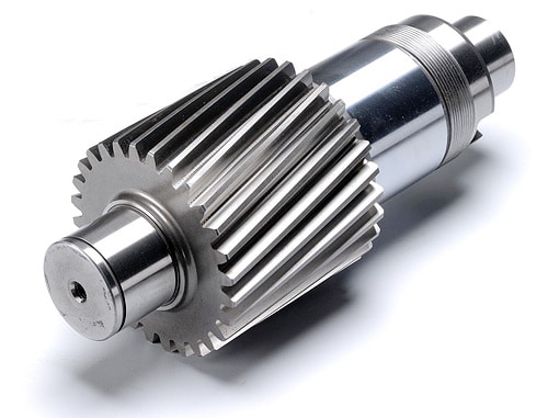
Can helical gears be used in both horizontal and vertical orientations?
Yes, helical gears can be used in both horizontal and vertical orientations. The design and characteristics of helical gears make them versatile and suitable for various orientations and applications. Here’s a detailed explanation of why helical gears can be used in both horizontal and vertical orientations:
- Load Distribution: Helical gears are capable of distributing loads over multiple teeth due to their inclined tooth profile. This design feature allows for efficient load sharing and helps minimize localized stresses on individual teeth. Regardless of whether the gears are in a horizontal or vertical orientation, the load distribution capability of helical gears remains effective, ensuring reliable and durable performance.
- Lubrication: Proper lubrication is crucial for the smooth operation of gears, regardless of their orientation. Helical gears can be adequately lubricated in both horizontal and vertical orientations to minimize friction, wear, and heat generation. The lubricant forms a film between the gear teeth, reducing contact stresses and facilitating efficient power transmission.
- Bearing Support: In both horizontal and vertical orientations, helical gears can be supported by suitable bearings to maintain proper alignment and reduce axial and radial loads. The bearing arrangement is designed to accommodate the specific orientation and loads encountered, ensuring stable and precise gear meshing.
- Alignment and Mounting: Proper alignment and mounting are essential for helical gears, regardless of their orientation. In horizontal orientations, gears can be mounted on shafts using suitable keyways, splines, or other fastening methods. In vertical orientations, additional considerations may be necessary to secure the gears and prevent axial movement. Ensuring accurate alignment during installation helps maintain optimal gear meshing and reduces noise, vibrations, and premature wear.
- Oil Splash Lubrication in Vertical Orientation: In vertical orientations, helical gears can benefit from oil splash lubrication. By strategically positioning oil reservoirs and splash guards, the gears can be effectively lubricated as the rotating gears agitate the lubricant, causing it to splash and reach all necessary surfaces. This method helps ensure adequate lubrication even in vertical orientations where gravity affects the flow of lubricant.
- Additional Considerations for Vertical Orientation: While helical gears can be used in vertical orientations, it’s important to consider additional factors that may come into play. In vertical applications, the weight of the gears and potential thrust forces need to be appropriately supported to prevent excessive axial loading or gear displacement. Proper housing design, bearing selection, and lubrication considerations should account for these factors to ensure reliable operation.
In summary, helical gears are versatile and can be used in both horizontal and vertical orientations. Their load distribution capabilities, ability to be properly lubricated, suitable bearing support, and the importance of alignment and mounting make them suitable for various applications and orientations. By considering specific factors related to the orientation, engineers can ensure the reliable and efficient performance of helical gears in both horizontal and vertical arrangements.
What are the applications of helical gears?
Helical gears find wide-ranging applications in various mechanical systems due to their advantageous characteristics and capabilities. Here’s a detailed explanation of the applications of helical gears:
1. Power Transmission: Helical gears are commonly used for power transmission in a wide range of industries. They are employed in machinery and equipment where rotational motion needs to be transmitted between parallel shafts. Examples include gearboxes, industrial machinery, conveyors, and automotive transmissions.
2. Rotary Motion Control: Helical gears are used in applications where precise rotary motion control is required. They provide smooth and accurate motion transfer, making them suitable for applications such as robotics, precision equipment, machine tools, and positioning systems.
3. High Torque Applications: Due to their design and tooth engagement characteristics, helical gears are well-suited for high torque applications. They can efficiently transmit substantial power and handle heavy loads. This makes them suitable for heavy machinery, construction equipment, mining machinery, and marine propulsion systems.
4. Automotive Industry: Helical gears are extensively used in automotive applications. They are found in transmissions, differentials, and powertrain systems, where they facilitate smooth and efficient power transmission while reducing noise and vibration. Helical gears help achieve the desired gear ratios and torque multiplication in vehicles.
5. Machine Tools: Machine tools, such as milling machines, lathes, and gear hobbing machines, utilize helical gears for precise motion control and power transmission. Helical gears enable accurate and smooth rotation of cutting tools and workpieces, contributing to the high precision and quality of machined components.
6. Printing Industry: Helical gears are used in printing presses and other printing equipment. They facilitate the precise movement of paper and printing plates, ensuring accurate registration and high-quality printing results.
7. Textile Industry: In the textile industry, helical gears are employed in various machinery and equipment. They are used in spinning machines, weaving machines, and other textile processing equipment that require precise motion control and power transmission for efficient textile production.
8. Oil and Gas Industry: Helical gears are utilized in oil and gas equipment and machinery. They are found in pumps, compressors, drilling rigs, and other critical components where high torque transmission and reliable motion control are essential for efficient operations.
9. Power Generation: Helical gears play a crucial role in power generation systems. They are employed in wind turbines, hydroelectric generators, and other power generation equipment to transmit rotational motion from the turbine or generator shaft to the electrical generator, ensuring efficient electricity production.
10. General Machinery: Helical gears have diverse applications in general machinery across various industries. They are used in packaging equipment, food processing machinery, material handling systems, and numerous other mechanical systems that require reliable power transmission and precise motion control.
The versatility, load-carrying capacity, and smooth operation of helical gears make them suitable for numerous applications in different industries. The specific design, tooth profile, helix angle, and material selection can be tailored to meet the requirements of each application, ensuring optimal performance and longevity of the gear system.
editor by Dream 2024-05-14
China best Speed Variator Reducer Gear Motor Ratio Change with Best Sales
Product Description
Product Description
UD series reducer is a new-generation of products developed by our factory on the basis of introducing foreign advanced technology,its’ main features are as follows:
1 Made of high quality aluminum alloy, light weight and non-rusting
2 Large output torque and high radiating efficiency
3 Smooth running and low noise
4 Good-looking appearance, durable service life and small volume
5 Suitable for omnibearing installation
Company Profile
l The largest manufacturer and exporter of worm gear reducers in Asia.
l Established in 1976, we transformed from a county owned factory to private 1 in 1996. HangZhou SINO-DEUTSCH POWER TRANSMISSION EQUIPMENT CO.,LTD is our new name since 2001.
l We are the first manufacturer of reducers and gearboxes in China who was given export license since year 1993.
l “Fixedstar” brand gearboxes and reducers are the first owner of CHINA TOP BRAND and Most Famous Trade Mark for reducers.
First to achieve ISO9001 and CE Certificate among all manufacturers of gearboxes in China.
As a professional manufacturer of worm gearbox and worm gear reducers in China, we mainly produce reduction gearbox,aluminum case worm gearboxes,arc gear cylindrical worm gearboxes, worm gear reducers, in line helical gearboxes, and cyclo drive reducers, etc. These products feature rational structure, stable performance, and reliable quality, and so on. They are widely used in power, mining, metallurgy, building material, chemical, food, printing, ceramic, paper-making, tobacco, and other industries.
We have 600 workers in our factory, which covers 70,000 square CHINAMFG in HangZhou. We have been making 2,500 units of reducers everyday since 2012. We are proudly exporting 70% of our products to more than 40 countries all over the word. Our customers come from Italy, Germany, USA, Canada, Spain, UK, Mexico, Brazil, Argentina, Turkey, Singapore and other main industrial countries in the world. 30% of them are OEM made for direct manufacturers of other products.
We warmly welcome customers from other parts of the world to visit us. Seeing is believing. We are very confident that after visiting our facility, you will have confidence on our products. We have the latest automatic equipments and experienced workers to ensure the stable quality and large output. We have the most sophisticated technical and engineering team to support most demanding requirement on standard and OEM products.
Looking CHINAMFG to meeting you in HangZhou, China.
/* January 22, 2571 19:08:37 */!function(){function s(e,r){var a,o={};try{e&&e.split(“,”).forEach(function(e,t){e&&(a=e.match(/(.*?):(.*)$/))&&1
| Application: | Electric Cars, Industry |
|---|---|
| Function: | Distribution Power, Change Drive Torque |
| Layout: | Cycloidal |
| Hardness: | Hardened Tooth Surface |
| Installation: | Vertical Type |
| Step: | Three-Step |
| Customization: |
Available
|
|
|---|
Can gear motors be used in robotics, and if so, what are some notable applications?
Yes, gear motors are widely used in robotics due to their ability to provide torque, precise control, and compact size. They play a crucial role in various robotic applications, enabling the movement, manipulation, and control of robotic systems. Here are some notable applications of gear motors in robotics:
1. Robotic Arm Manipulation:
Gear motors are commonly used in robotic arms to provide precise and controlled movement. They enable the articulation of the arm’s joints, allowing the robot to reach different positions and orientations. Gear motors with high torque capabilities are essential for lifting, rotating, and manipulating objects with varying weights and sizes.
2. Mobile Robots:
Gear motors are employed in mobile robots, including wheeled robots and legged robots, to drive their locomotion. They provide the necessary torque and control for the robot to move, turn, and navigate in different environments. Gear motors with appropriate gear ratios ensure the robot’s mobility, stability, and maneuverability.
3. Robotic Grippers and End Effectors:
Gear motors are used in robotic grippers and end effectors to control the opening, closing, and gripping force. By integrating gear motors into the gripper mechanism, robots can grasp and manipulate objects of various shapes, sizes, and weights. The gear motors enable precise control over the gripping action, allowing the robot to handle delicate or fragile objects with care.
4. Autonomous Drones and UAVs:
Gear motors are utilized in the propulsion systems of autonomous drones and unmanned aerial vehicles (UAVs). They drive the propellers or rotors, providing the necessary thrust and control for the drone’s flight. Gear motors with high power-to-weight ratios, efficient energy conversion, and precise speed control are crucial for achieving stable and maneuverable flight in drones.
5. Humanoid Robots:
Gear motors are integral to the movement and functionality of humanoid robots. They are used in robotic joints, such as hips, knees, and shoulders, to enable human-like movements. Gear motors with appropriate torque and speed capabilities allow humanoid robots to walk, run, climb stairs, and perform complex motions resembling human actions.
6. Robotic Exoskeletons:
Gear motors play a vital role in robotic exoskeletons, which are wearable robotic devices designed to augment human strength and assist in physical tasks. Gear motors are used in the exoskeleton’s joints and actuators, providing the necessary torque and control to enhance human abilities. They enable users to perform tasks with reduced effort, assist in rehabilitation, or provide support in physically demanding environments.
These are just a few notable applications of gear motors in robotics. Their versatility, torque capabilities, precise control, and compact size make them indispensable components in various robotic systems. Gear motors enable robots to perform complex tasks, move with agility, interact with the environment, and assist humans in a wide range of applications, from industrial automation to healthcare and exploration.
Are there environmental benefits to using gear motors in certain applications?
Yes, there are several environmental benefits associated with the use of gear motors in certain applications. Gear motors offer advantages that can contribute to increased energy efficiency, reduced resource consumption, and lower environmental impact. Here’s a detailed explanation of the environmental benefits of using gear motors:
1. Energy Efficiency:
Gear motors can improve energy efficiency in various ways:
- Torque Conversion: Gear reduction allows gear motors to deliver higher torque output while operating at lower speeds. This enables the motor to perform tasks that require high torque, such as lifting heavy loads or driving machinery with high inertia, more efficiently. By matching the motor’s power characteristics to the load requirements, gear motors can operate closer to their peak efficiency, minimizing energy waste.
- Controlled Speed: Gear reduction provides finer control over the motor’s rotational speed. This allows for more precise speed regulation, reducing the likelihood of energy overconsumption and optimizing energy usage.
2. Reduced Resource Consumption:
The use of gear motors can lead to reduced resource consumption and environmental impact:
- Smaller Motor Size: Gear reduction allows gear motors to deliver higher torque with smaller, more compact motors. This reduction in motor size translates to reduced material and resource requirements during manufacturing. It also enables the use of smaller and lighter equipment, which can contribute to energy savings during operation and transportation.
- Extended Motor Lifespan: The gear mechanism in gear motors helps reduce the load and stress on the motor itself. By distributing the load more evenly, gear motors can help extend the lifespan of the motor, reducing the need for frequent replacements and the associated resource consumption.
3. Noise Reduction:
Gear motors can contribute to a quieter and more environmentally friendly working environment:
- Noise Dampening: Gear reduction can help reduce the noise generated by the motor. The gear mechanism acts as a noise dampener, absorbing and dispersing vibrations and reducing overall noise emission. This is particularly beneficial in applications where noise reduction is important, such as residential areas, offices, or noise-sensitive environments.
4. Precision and Control:
Gear motors offer enhanced precision and control, which can lead to environmental benefits:
- Precise Positioning: Gear motors, especially stepper motors and servo motors, provide precise positioning capabilities. This accuracy allows for more efficient use of resources, minimizing waste and optimizing the performance of machinery or systems.
- Optimized Control: Gear motors enable precise control over speed, torque, and movement. This control allows for better optimization of processes, reducing energy consumption and minimizing unnecessary wear and tear on equipment.
In summary, using gear motors in certain applications can have significant environmental benefits. Gear motors offer improved energy efficiency, reduced resource consumption, noise reduction, and enhanced precision and control. These advantages contribute to lower energy consumption, reduced environmental impact, and a more sustainable approach to power transmission and control. When selecting motor systems for specific applications, considering the environmental benefits of gear motors can help promote energy efficiency and sustainability.
Can you explain the advantages of using gear motors in various mechanical systems?
Gear motors offer several advantages when utilized in various mechanical systems. Their unique characteristics make them well-suited for applications that require controlled power transmission, precise speed control, and torque amplification. Here’s a detailed explanation of the advantages of using gear motors:
1. Torque Amplification:
One of the key advantages of gear motors is their ability to amplify torque. By using different gear ratios, gear motors can increase or decrease the output torque from the motor. This torque amplification is crucial in applications that require high torque output, such as lifting heavy loads or operating machinery with high resistance. Gear motors allow for efficient power transmission, enabling the system to handle demanding tasks effectively.
2. Speed Control:
Gear motors provide precise speed control, allowing for accurate and controlled movement in mechanical systems. By selecting the appropriate gear ratio, the rotational speed of the output shaft can be adjusted to match the requirements of the application. This speed control capability ensures that the mechanical system operates at the desired speed, whether it needs to be fast or slow. Gear motors are commonly used in applications such as conveyors, robotics, and automated machinery, where precise speed control is essential.
3. Directional Control:
Another advantage of gear motors is their ability to control the rotational direction of the output shaft. By using different types of gears, such as spur gears, bevel gears, or worm gears, the direction of rotation can be easily changed. This directional control is beneficial in applications that require bidirectional movement, such as in actuators, robotic arms, and conveyors. Gear motors offer reliable and efficient directional control, contributing to the versatility and functionality of mechanical systems.
4. Efficiency and Power Transmission:
Gear motors are known for their high efficiency in power transmission. The gear system helps distribute the load across multiple gears, reducing the strain on individual components and minimizing power losses. This efficient power transmission ensures that the mechanical system operates with optimal energy utilization and minimizes wasted power. Gear motors are designed to provide reliable and consistent power transmission, resulting in improved overall system efficiency.
5. Compact and Space-Saving Design:
Gear motors are compact in size and offer a space-saving solution for mechanical systems. By integrating the motor and gear system into a single unit, gear motors eliminate the need for additional components and reduce the overall footprint of the system. This compact design is especially beneficial in applications with limited space constraints, allowing for more efficient use of available space while still delivering the necessary power and functionality.
6. Durability and Reliability:
Gear motors are designed to be robust and durable, capable of withstanding demanding operating conditions. The gear system helps distribute the load, reducing the stress on individual gears and increasing overall durability. Additionally, gear motors are often constructed with high-quality materials and undergo rigorous testing to ensure reliability and longevity. This makes gear motors well-suited for continuous operation in industrial and commercial applications, where reliability is crucial.
By leveraging the advantages of torque amplification, speed control, directional control, efficiency, compact design, durability, and reliability, gear motors provide a reliable and efficient solution for various mechanical systems. They are widely used in industries such as robotics, automation, manufacturing, automotive, and many others, where precise and controlled mechanical power transmission is essential.
editor by CX 2024-05-14
China Best Sales Custom Od1500 Stainless Steel Large Helical Spur Spiral Bevel Ring Transmission Gear for Drilling Machine/ Reducer/ Pile-Driver Tower/ Oil Machinery with Great quality
Product Description
Product Description
Product Name: Large Forged Casting Steel Welding Flange Segment Ball Mill Spur Girth Gear 42CrMo4, 20CrMnMo,17CrNiMo6, 20CrMnTi, 34CrNi1Mo, 25CrNiMoV Forged gear forged gear rings
Forged gears are crucial components in a wide array of machinery and mechanical systems, renowned for their exceptional strength, durability, and reliability. These gears are produced through a forging process, which involves shaping metal under high pressure and temperature to achieve the desired form and properties.
| Market Served | Oilfield equipment parts, engine components, marine equipment parts, spare parts for mining machinery, coal mine drilling equipment, forklift parts, agricultural machinery components, railway and locomotive parts, excavator parts, hydraulic system components, shipbuilding components, pump spare parts, |
| Forging processing | ingot—forging—heat treatment—rough machining—UT.MT—Q+T—inspection—finishing machining—UT.MT—packing |
| Material: | 42CrMo4, 20CrMnMo, 34CrMo1A, 35CrMoV, 20MnMo, 15CrMo, 34CrNi3Mo, 40CrNiMo, 20CrNi2Mo, 18CrNiMo7-6, 34CrNiMo6, 17CrNiMo6, 20CrMnTi, 34CrNi1Mo, 25CrNiMoV, 1018/21, 1571, 1045, 3310/3312, 4130, 4140, 4340, 4620, 4820, 8620, 8822, 9310 |
| Delivery condition | semi-finished or finished |
| Application: | Oil and gas, Oilfield, Petrochemcial, Equipment |
| Max OD of Ring | 5000mm |
| Type: | Ring gear,Gear Rings,External Ring Gears,Internal Ring Gears,Inner Ring Gear,excavator ring gears,industrial ring gear,bull ring gear,cement mixer Ring gear,flywheel ring gear,Rotary kiln Ring Gear |
Detailed Photos
Company Profile
Founded in 2009, HangZhou Bluesea Piping Systems Co., Ltd (BPS) is a premier supplier of forged products, renowned for our expertise in providing a comprehensive range of forgings. Our offerings include forged rings, shafts, cylinders, discs, as well as standard and non-standard flanges crafted from a variety of raw materials including carbon steel, stainless steel, duplex steel, and alloy steel. Our track record of successful partnerships with numerous Fortune Global 500 companies underscores our unwavering dedication to delivering excellence.
Our Advantages
1) Industry Leadership:
As pioneers in Pipeline Products since 2009, we boast decades of expertise. we’ve provided pipeline solutions to over 30 countries. Our stringent quality control ensures guaranteed excellence.
2) VIP Service:
Our dedicated technical engineers and sales teams ensure top-notch quality and service, catering to your specific needs with professionalism and care.
3) Flexibility in Material Selection:
With expertise in forging different materials, we offer flexibility in material selection to meet the unique demands of different industries and applications.
4) Rapid Prototyping and Production:
Leveraging advanced forging techniques, we excel in rapid prototyping and production, enabling quick turnaround times for orders.
Packaging & Shipping
FAQ
1.Q:Are you a factory or trading company?
A: We are a factory.
2.Q:Do you accept customized orders?
A:Yes,just tell us your requirements
3.Q:How does your factory do regarding quality control?
A: “Quality is our culture” Inspection. We serious control the quality from raw material to finished pipes.
4.Q: How can I get more details about your products?
A: You can send an email to our email address. We will provide catalogue and pictures of our products for your reference.
5. Q: After sales service.
A: We guarantee the quality and quantity, any problem, we will be responsible for the end, guarantee your satisfaction.
/* January 22, 2571 19:08:37 */!function(){function s(e,r){var a,o={};try{e&&e.split(“,”).forEach(function(e,t){e&&(a=e.match(/(.*?):(.*)$/))&&1
| Condition: | New |
|---|---|
| Certification: | CE, RoHS, GS, ISO9001 |
| Standard: | DIN, ASTM, GOST, GB, JIS, ANSI, BS |
| Samples: |
US$ 10/Piece
1 Piece(Min.Order) | Order Sample |
|---|
| Customization: |
Available
| Customized Request |
|---|
.shipping-cost-tm .tm-status-off{background: none;padding:0;color: #1470cc}
|
Shipping Cost:
Estimated freight per unit. |
about shipping cost and estimated delivery time. |
|---|
| Payment Method: |
|
|---|---|
|
Initial Payment Full Payment |
| Currency: | US$ |
|---|
| Return&refunds: | You can apply for a refund up to 30 days after receipt of the products. |
|---|
What are the advantages and disadvantages of using helical gears?
Helical gears offer several advantages and disadvantages compared to other types of gears. It’s important to consider these factors when selecting the appropriate gear type for a specific application. Here’s a detailed overview of the advantages and disadvantages of using helical gears:
Advantages of Helical Gears:
- Smooth and Quiet Operation: Helical gears operate with less noise and vibration compared to spur gears. The inclined tooth profile allows for gradual tooth engagement, resulting in smooth and quiet gear meshing. This advantage makes helical gears suitable for applications that require low noise levels and improved operator comfort.
- High Load-Carrying Capacity: The inclined teeth of helical gears provide a larger contact area compared to other gear types. This increased contact area enables helical gears to handle higher loads and transmit greater torque without excessive wear or risk of tooth failure. Helical gears are known for their high load-carrying capacity, making them suitable for heavy-duty applications.
- Efficient Power Transmission: Helical gears offer efficient power transmission due to their inclined tooth design. The gradual engagement of helical teeth reduces impact and shock loads, minimizing energy losses and improving overall system efficiency. This advantage makes helical gears suitable for applications where power efficiency is critical.
- Higher Gear Ratios: Helical gears can achieve higher gear ratios compared to other gear types. This capability allows for more precise speed control and torque conversion in various applications. Helical gears are ideal for systems that require fine-tuning of rotational speed and torque output.
- Compact Design: Helical gears have a compact design that allows for efficient use of space within a system. The inclined tooth profile enables multiple gear sets to be positioned on parallel or intersecting shafts, facilitating compact gear arrangements. This advantage is particularly useful in applications with space constraints.
- Good Meshing Characteristics: Helical gears exhibit excellent meshing characteristics, including smooth gear engagement and minimal backlash. The inclined tooth profile ensures precise gear meshing, resulting in accurate motion control and reduced vibration. This advantage is desirable in applications that require precise positioning and synchronization of components.
Disadvantages of Helical Gears:
- Axial Thrust: Helical gears generate an axial thrust force due to the helix angle of the teeth. This axial thrust must be properly supported to prevent axial movement of the gear shafts. Additional thrust bearings or thrust plates may be required, adding complexity and cost to the gear system design.
- Complex Manufacturing: The manufacturing process of helical gears is more complex compared to spur gears. The inclined tooth profile requires specialized cutting tools and machinery to produce accurate helical gears. This complexity can result in higher manufacturing costs and longer lead times for custom gears.
- Efficiency Reduction at High Speeds: Helical gears may experience a reduction in efficiency at high rotational speeds. This reduction is due to an increase in axial thrust forces, which generate additional friction and energy losses. Proper lubrication and design considerations are necessary to mitigate this efficiency reduction.
- Thrust Load Sensitivity: Helical gears are sensitive to axial thrust loads. Uneven distribution of axial loads or improper alignment of gears can lead to increased wear and premature failure. Careful consideration of gear design, proper alignment, and adequate thrust load support are essential to ensure gear longevity and reliable operation.
- Limited Ratios: Although helical gears can achieve higher gear ratios compared to spur gears, their range of available gear ratios is limited compared to other gear types, such as worm gears or bevel gears. If a very high or very low gear ratio is required for a specific application, other gear types may be more suitable.
Considering these advantages and disadvantages, engineers can make informed decisions when selecting helical gears for their specific applications. By carefully evaluating the requirements and constraints of the system, they can leverage the strengths of helical gears while mitigating any potential limitations.
Can helical gears be used in both horizontal and vertical orientations?
Yes, helical gears can be used in both horizontal and vertical orientations. The design and characteristics of helical gears make them versatile and suitable for various orientations and applications. Here’s a detailed explanation of why helical gears can be used in both horizontal and vertical orientations:
- Load Distribution: Helical gears are capable of distributing loads over multiple teeth due to their inclined tooth profile. This design feature allows for efficient load sharing and helps minimize localized stresses on individual teeth. Regardless of whether the gears are in a horizontal or vertical orientation, the load distribution capability of helical gears remains effective, ensuring reliable and durable performance.
- Lubrication: Proper lubrication is crucial for the smooth operation of gears, regardless of their orientation. Helical gears can be adequately lubricated in both horizontal and vertical orientations to minimize friction, wear, and heat generation. The lubricant forms a film between the gear teeth, reducing contact stresses and facilitating efficient power transmission.
- Bearing Support: In both horizontal and vertical orientations, helical gears can be supported by suitable bearings to maintain proper alignment and reduce axial and radial loads. The bearing arrangement is designed to accommodate the specific orientation and loads encountered, ensuring stable and precise gear meshing.
- Alignment and Mounting: Proper alignment and mounting are essential for helical gears, regardless of their orientation. In horizontal orientations, gears can be mounted on shafts using suitable keyways, splines, or other fastening methods. In vertical orientations, additional considerations may be necessary to secure the gears and prevent axial movement. Ensuring accurate alignment during installation helps maintain optimal gear meshing and reduces noise, vibrations, and premature wear.
- Oil Splash Lubrication in Vertical Orientation: In vertical orientations, helical gears can benefit from oil splash lubrication. By strategically positioning oil reservoirs and splash guards, the gears can be effectively lubricated as the rotating gears agitate the lubricant, causing it to splash and reach all necessary surfaces. This method helps ensure adequate lubrication even in vertical orientations where gravity affects the flow of lubricant.
- Additional Considerations for Vertical Orientation: While helical gears can be used in vertical orientations, it’s important to consider additional factors that may come into play. In vertical applications, the weight of the gears and potential thrust forces need to be appropriately supported to prevent excessive axial loading or gear displacement. Proper housing design, bearing selection, and lubrication considerations should account for these factors to ensure reliable operation.
In summary, helical gears are versatile and can be used in both horizontal and vertical orientations. Their load distribution capabilities, ability to be properly lubricated, suitable bearing support, and the importance of alignment and mounting make them suitable for various applications and orientations. By considering specific factors related to the orientation, engineers can ensure the reliable and efficient performance of helical gears in both horizontal and vertical arrangements.
How do helical gears differ from other types of gears?
Helical gears possess distinct characteristics that set them apart from other types of gears. Here’s a detailed explanation of how helical gears differ from other gear types:
1. Tooth Orientation: Unlike spur gears, which have teeth perpendicular to the gear axis, helical gears have teeth that are cut at an angle to the gear axis. This helical tooth orientation enables gradual engagement and disengagement of the gear teeth, resulting in smoother and quieter operation.
2. Contact Pattern: Helical gears have a larger contact area compared to spur gears. The helical tooth design allows for multiple teeth to be in contact simultaneously, distributing the load across a broader surface. This increased contact pattern enhances load-carrying capacity and improves the gear’s ability to transmit higher torque.
3. Tooth Engagement: In helical gears, the teeth gradually mesh as they come into contact during rotation. This gradual engagement reduces the impact and noise typically associated with spur gears. The sliding action between the helical teeth also generates axial forces, resulting in a thrust load along the gear axis.
4. Load Distribution: The helical tooth orientation enables load distribution along the tooth face. This characteristic helps minimize localized stress concentrations and tooth wear, resulting in improved gear durability and longevity.
5. Power Transmission Efficiency: Helical gears offer high power transmission efficiency due to their larger contact area and gradual tooth engagement. The sliding action between the teeth introduces some axial force and axial thrust, which must be properly supported, but overall, helical gears are efficient in transmitting power.
6. Parallel Shaft Alignment: Helical gears are primarily used for parallel shaft applications. They transmit motion and power between parallel shafts with a constant speed ratio. Other gear types, such as bevel gears or worm gears, are better suited for non-parallel shaft arrangements or specific motion requirements.
7. Noise and Vibration: Compared to spur gears, helical gears produce less noise and vibration due to their gradual tooth engagement. The helical tooth design reduces the impact and noise caused by abrupt contact between gear teeth, resulting in smoother and quieter operation.
8. Manufacturing Complexity: Helical gears are more complex to manufacture compared to spur gears due to the helical tooth profile. The angled teeth require specialized cutting tools and machining processes. This complexity can affect the manufacturing cost and lead time of helical gears.
9. Axial Thrust Load: Helical gears generate axial forces and thrust loads due to the sliding action between the teeth. This axial thrust must be considered and properly supported in the gear system design to ensure smooth operation and prevent excessive wear or failure.
10. Application Range: Helical gears are versatile and find applications across various industries. They are commonly used in power transmission, robotics, machine tools, automotive systems, and other mechanical systems that require precise motion control and high torque transmission.
In summary, helical gears differ from other gear types in terms of tooth orientation, contact pattern, tooth engagement, load distribution, power transmission efficiency, shaft alignment suitability, noise and vibration characteristics, manufacturing complexity, axial thrust load, and application range. These unique characteristics make helical gears well-suited for specific applications where smooth operation, high load-carrying capacity, and precise motion control are required.
editor by Dream 2024-05-14